Train Simulator Controller: Real ATP-Enabled Speedometer
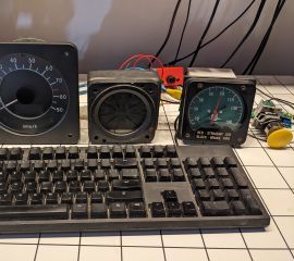
I’m building a physical dashboard to control Train Simulator, from master controller to an AWS sunflower to an air gauge, and everything in between. I initially aimed to replicate the dashboard of the UK Class 80x high-speed train, later adjusting that goal to a space-efficient Class 80x-like dashboard. I started this project by trying to build my own speedometer, experimenting with a stepper motor used for automotive instruments that I later integrated into a CAN-controlled air gauge. Thanks to UK eBay, I eventually got my hands on not only real UK train speedometers, but a couple of speedometers that are fitted with the LEDs and alphanumeric display necessary for Automatic Train Protection (ATP). Like ACSES, it automatically applies the brakes if it judges the driver (engineer for us US folks) is not slowing sufficiently for an upcoming speed limit. This system uses green and amber LEDs on the speedometer to indicate speed limits: solid green LEDs at the appropriate speed on the dial for the current Maximum Authorized Speed (MAS), flashing green for an upcoming change in the speed limit, and flashing amber for the “release speed” under which the system will no longer make a brake application. The 3-character alphanumeric display is used in the prototype to display status messages, including about why the brakes were applied, but I wanted to use it to display the current speed and the speed trend (accelerating or decelerating), like the digital speedometer in the Class 395.
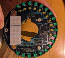
Getting these real speedometers working with Train Simulator was a particularly fun proposition, because no documentation existed about how they are controlled that I could find on the public internet. Two terminals provide an obvious analog current-controlled input for the needle, but an opaque 35-pin DIN socket (a wider sibling of the now-thoroughly retired 25-pin PC parallel port) provides an interface to the LEDs around the face and to the three alphanumeric digits in the center. I didn’t want to send random voltages through what could be a sensitive driver circuit, so the clear next step was disassembly. I painstakingly documented the disassembly process to make sure I would be able to put it back together again, and when I got to the PCB, I took enough photos that I hoped I could follow traces from the 35-pin DIN socket to the ICs or LEDs they control, of course also electrically tracing the connecctions. A few selected photos from that disassembly:
I started my investigation with an ATP-enabled speedometer with a indicated top speed of 90mph, apparently used in equipment not allowed to go over 75mph, but I later needed to disassemble the 120mph version I acquired to verify how to control the extra LEDs in this higher-speed speedometer. I discovered that each speedometer uses three ribbon cables to connect the DIN socket with the PCB, corresponding to three separate areas of the board used for the LED “rows”, LED “columns”, and the ICs that drive the alphanumeric display. As “rows” and “columns” imply, the LEDs around the perimeter of the meter are arranged in an electrical matrix, such that only 2 * sqrt(N) lines are required to control N LEDs. For example, a 10x10 array can be controlled by just 20 lines, by selecting one row, powering some set of the 10 columns corresponding to the LEDs to be illuminated in that row, and repeating rapidly for every row. These LEDs are much the same: the combined set of green and amber LEDs are arranged in a conceptual 5-row, 7-column grid, so I resolved to use Serial-to-Parallel shift registers to control them with even fewer than the 12 GPIO lines of my CAN controller that would otherwise be required. The alphanumeric LED arrays are more complex: a pair of 74HCT541 line buffers/shift registers feed three ams-OSRAM DLO7135 displays, surprisingly sophisticated units that accept a clocked, parallel 7-bit character code and display it according to an internal, read-only character table.
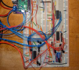
I wanted to control both the speed LEDs and the alphanumeric display, and like all my other instruments, I wanted my CAN controller to be the brains behind the unit. I therefore resolved to design a new PCB I could “piggyback” on my CAN controller and would plug neatly into the DIN socket. To avoid wasted time, money, and parts, I started by sketching a design with four shift registers and all of the necessary support components that I laid out on a breadboard. The left side shows the beginning of assembly, the right side the completed prototype:
Planning and testing on a breadboard was a good choice: as I debugged the hardware and wrote the relevant firmware module for the CAN controller, I encountered a few bumps (this was supposed to say “Hel”, as in “Hello, World!”):
Finally, I got the hardware and software working, and was ready to turn the design into a PCB.
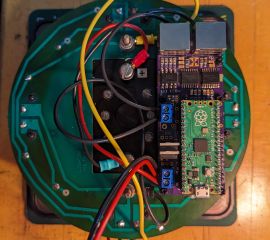
My designs often have the telltale purple of OSHPark PCBs, but this time I ordered the boards from JLCPCB, then assembled them with generally smaller components than I have hand-soldered before, a necessity to fit the four shift registers, 12 LED-driving transistors with associated resistors, plus a trimmer for fine calibration of the analog speedometer needle. I also left holes for future screws to secure this to the speedometer, and it stacks neatly with my CAN bus controller, connecting via the 11-pin GPIO header on the controller. For future configurability and compatibility, it includes three 2-pin jumpers to set the type of speedometer to which the speedometer controller is connected. The PCB design in progress, followed by the finished board, and the installed stack:
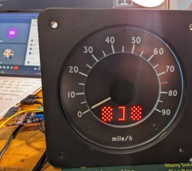
Finally, I could connect the speedometer to my setup (using the 120mph version), drive Class 80x trains around the UK railway network, and get digital and analog speed indications plus useful speed limit information!
 ATP-enabled speedometer running with active ATP on a Class 80x LNER Azuma

