Train Simulator Controller: CAN-Connected Air Gauge
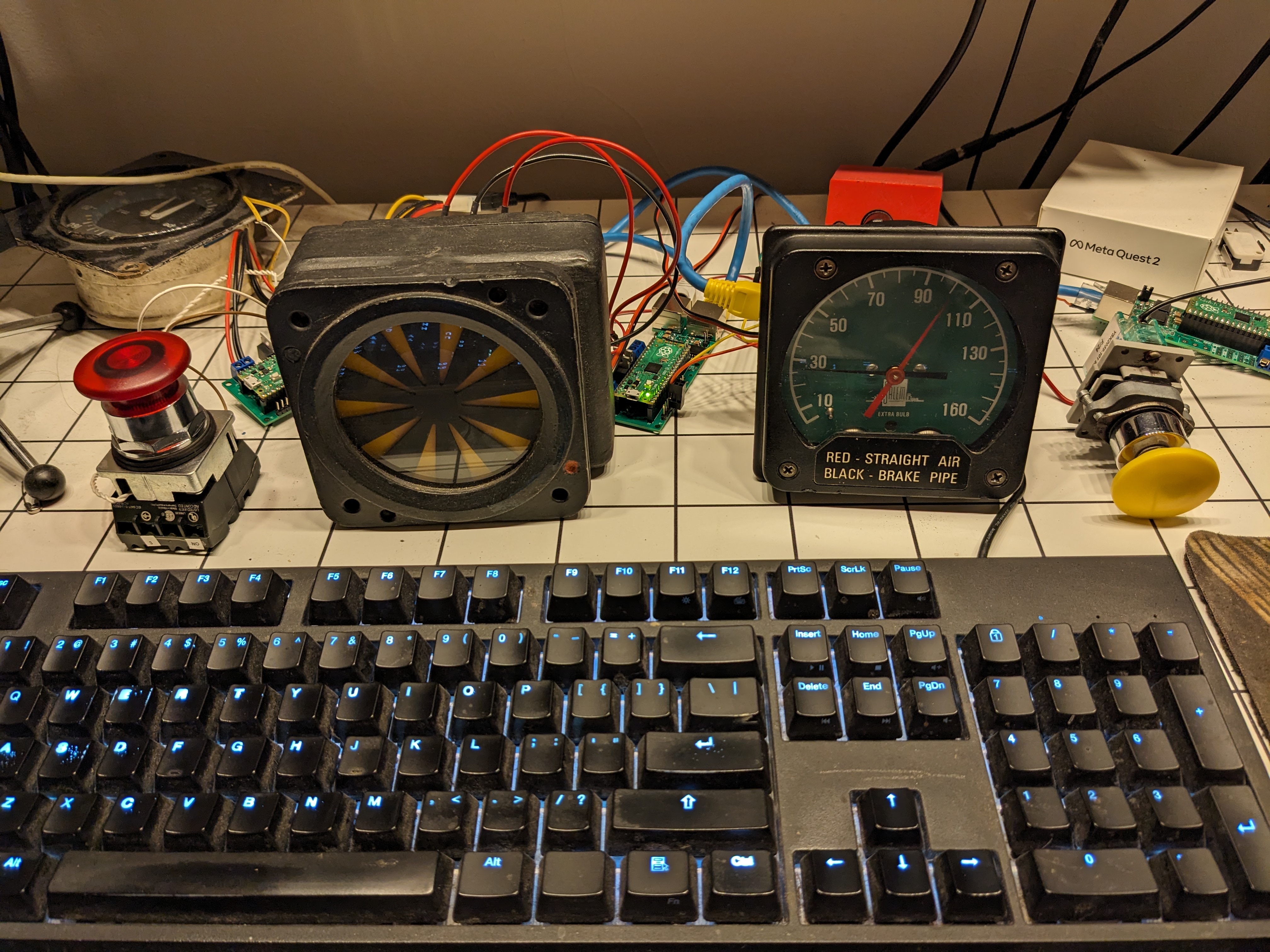
In my ongoing quest to build a physical cab dashboard to control Train Simulator, an important set of components are the gauges that tell me what’s going on with the train. I already showed off the internals of an AWS sunflower, which will become CAN bus-connected in a future blog post, early experiments with a speedometer, and next up is an air pressure gauge or air gauge. In a self-powered train or locomotive, one or more air gauges are vital instruments to tell the engineer (or driver, for my UK readers) information about the air-driven braking system. In modern trains, compressed air pressure is usually used to push the brake shoes against the tread of steel wheels, or calipers around the disks of a disk brake. At the very least, the engineer or driver needs to know that there is sufficient air pressure available to be applied to the brakes if needed, and also needs to know how much pressure is being used to apply the brakes to the wheels right now. The higher the pressure in the brake cylinder, the stronger the braking force and the higher the deceleration. Apply and release the brakes too often, and not enough pressure will remain in the air reservoirs, such as the main reservoir, to apply the brakes and stop the train: the air compressor(s) take time to restore that pressure.
Some multiple-unit (MU) equipment has a single two-needle gauge showing the pressure in the main reservoir and the brake pipe: as the pressure in the brake pipe falls, the braking force increases. Reduce the brake pipe pressure to zero, and the full force of emergency braking is applied. Locomotives frequently have two two-needle gauges, which need to convey four pressures: the main reservoir (MR, your primary source of compressed air), the equalizing reservoir (EQ/ER, an indirect pressure that ultimately controls the train’s brake pipe pressure), the locomotive’s brake cylinder pressure (BC), and the train’s brake pipe pressure (BP). The brake cylinder pressure is at zero pressure when brakes are fully released, and the function of the equalizing reservoir is outside the scope of this blog post. Wikipedia has a decent explanation.
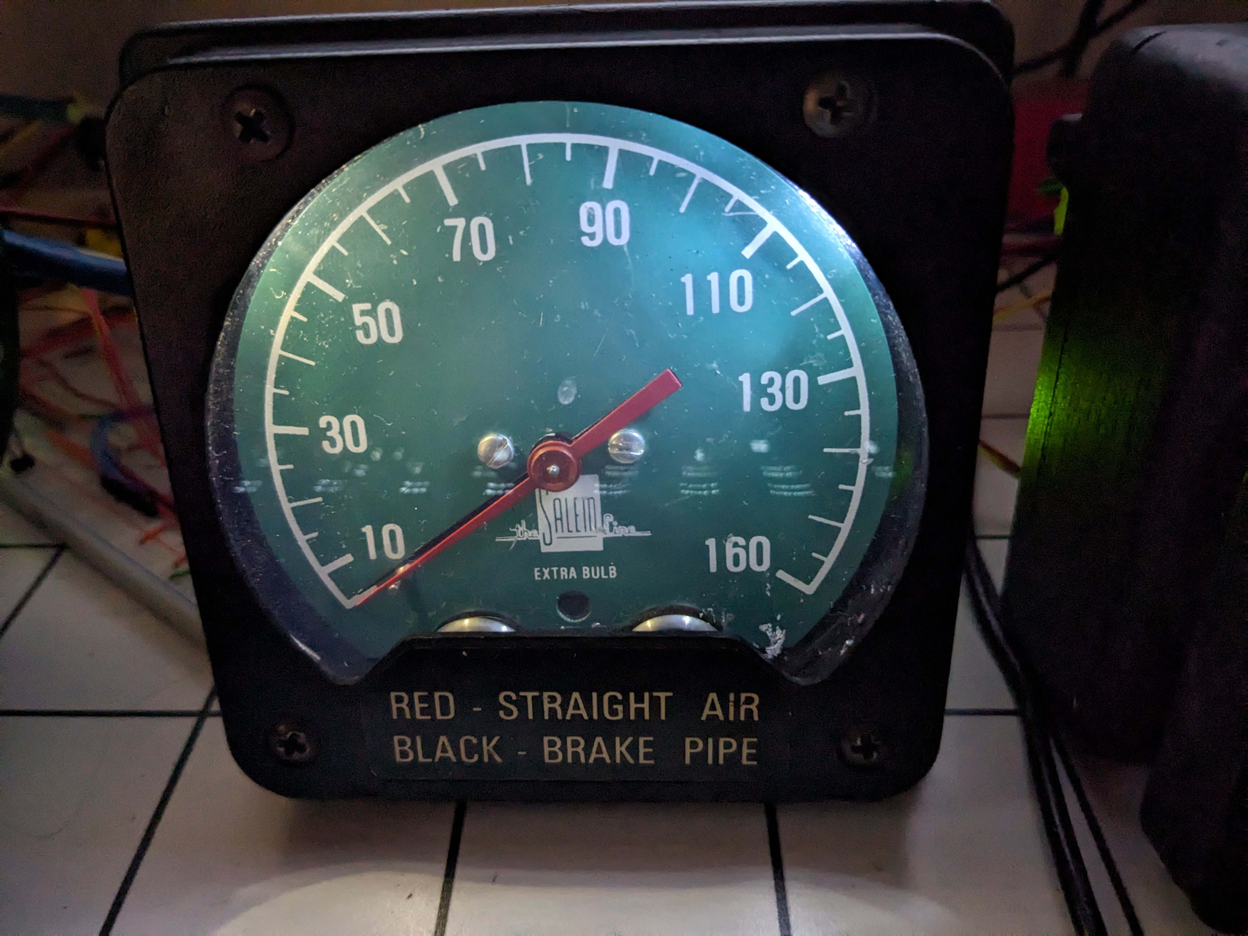
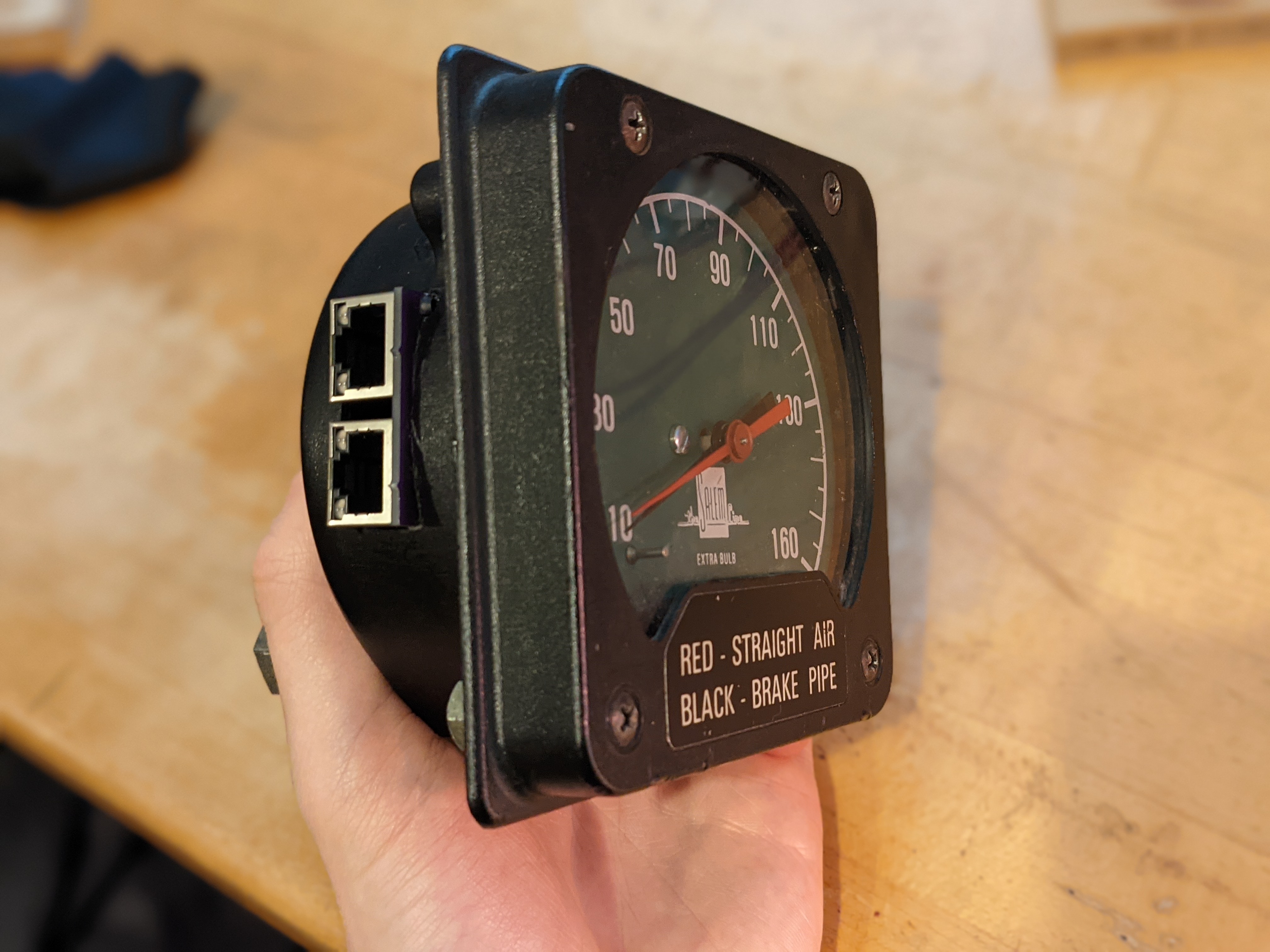
I started this part of the project with a two-needle air gauge from Graham-White, now a division of Wabtec, similar to this one. While the legend on the front of my gauge indicates that the red hand was for the straight air (almost certainly locomotive brake cylinder) and the black for trainline brake pipe, I tend to run primarily passenger service with MUs or with UK power cars that don’t have separate independent and automatic brakes. Therefore, I’m currently using the red needle to indicate main reservoir (MR) pressure, and the black needle to indicate brake cylinder (BC) pressure.
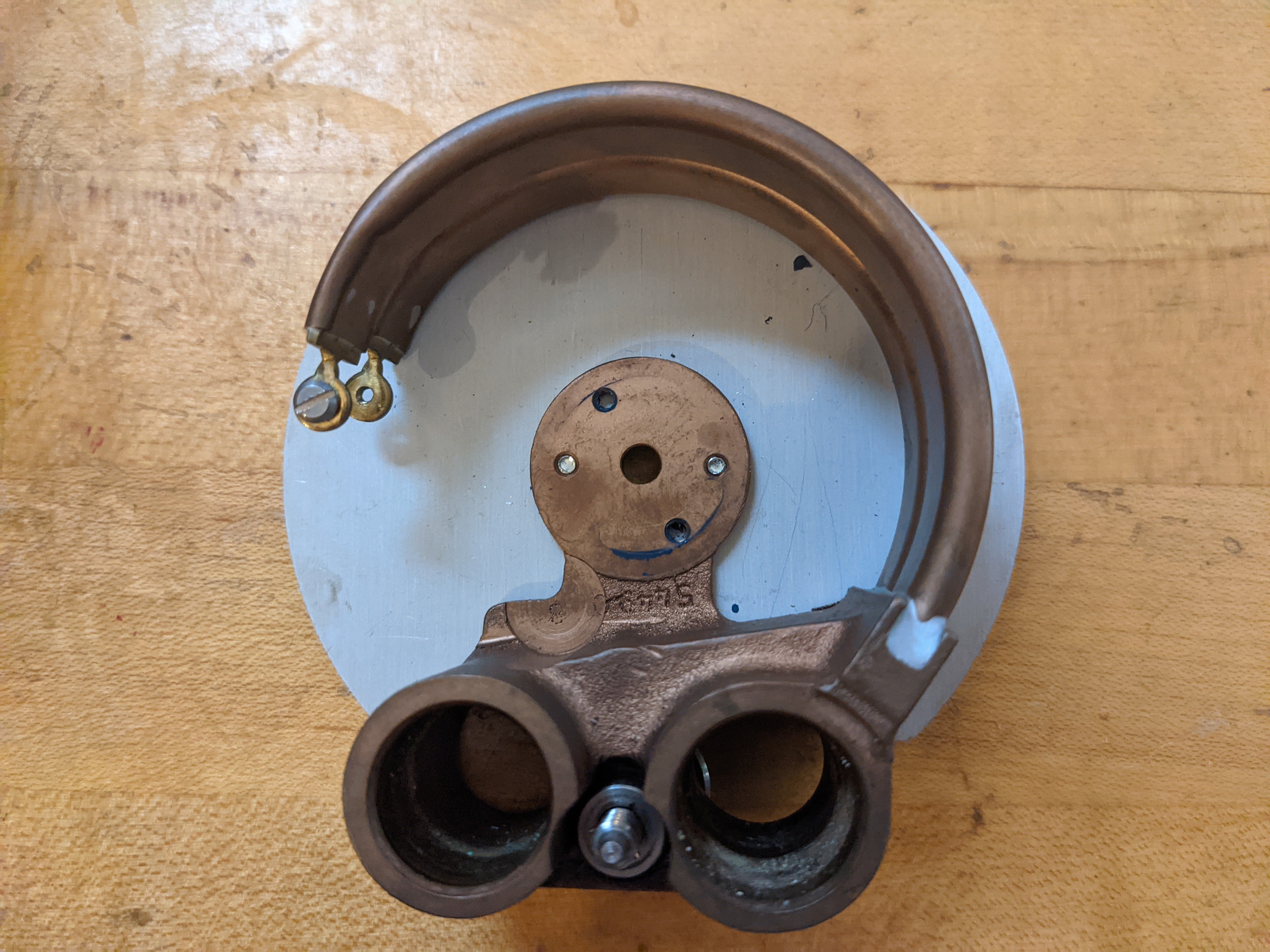
These gauges are masterpieces of miniature mechanisms: air pressure straightens brass tubes, which pulls a curve rack gear against a pinion gear, rotating a needle. Indeed, the two-needle coaxial version cleverly fits two such mechanisms together. I had the unenviable task of gutting my beautiful example, reducing it to the plastic case, metal face, needles, and plexiglass faceplate. Here’s the back of the metal face, showing the Bourdon tubes, the central hole through which the needle axes go, and the two large apertures where air pressure from the rest of the air system enters.
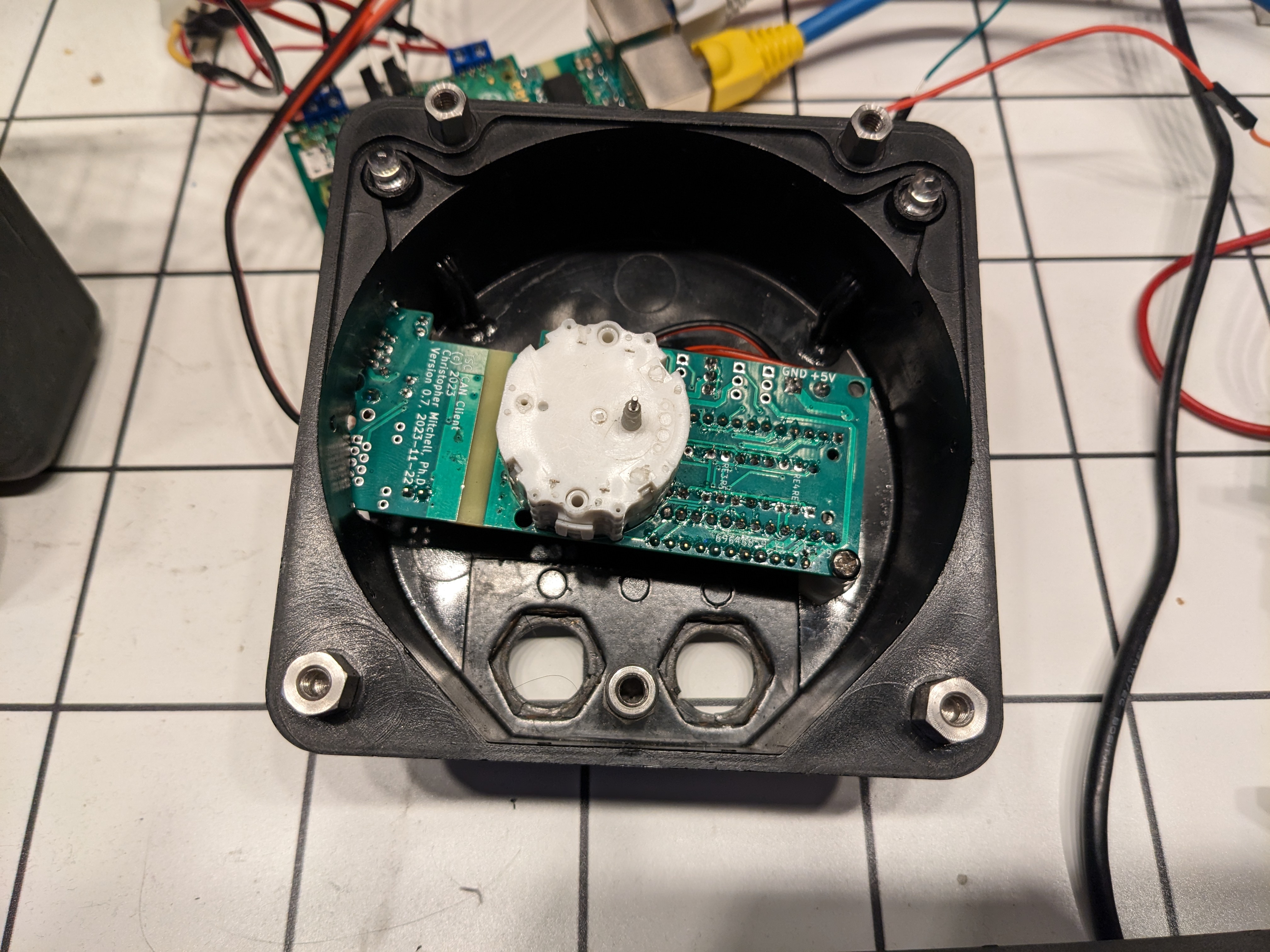
As discussed at some length in my first post about this project, I knew I would need to control stepper motors for various gauges. I tried to control the stepper motor in that post’s off-the-shelf tachometer, and later found myself with popular X27 and X40 (single-axis and biaxial, respectively) stepper motors commonly used in automotive instruments. In fact, the CAN controller board design in the previous post has an explicit footprint right on the board for soldering either stepper motor. These unusual motors are controlled differently from a normal two-coil stepper motor, with six phases instead of eight: interesting discussion can be found, for example, on the Arduino forum. At length I modified my previous Raspberry Pi Pico stepper driver to be able to properly control these motors, and then designed a way to offload stepper control to the Pi Pico’s second core while continuing CAN communication on the first core, an aspect of the CAN controller firmware that I hope to detail in a future post. Before I hooked up the CAN bus control, I ran tests to make sure the two needles moved as expected with the X27/X40 stepper library.
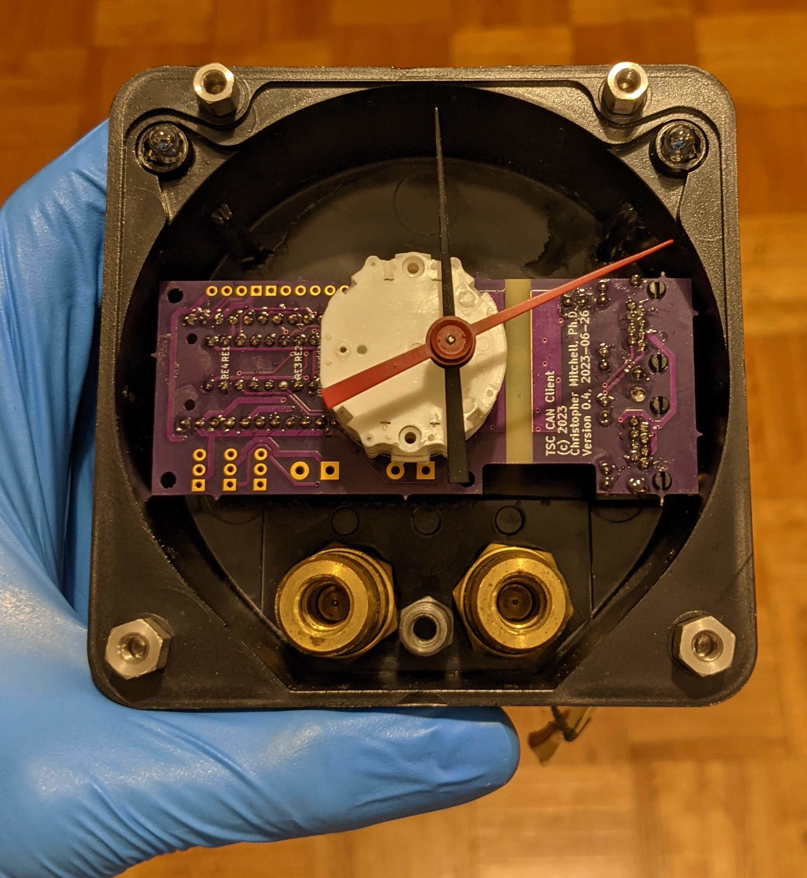
I was pleased to see that the CAN controller board fit neatly into the air gauge housing; unfortunately, the axes of the X40 stepper motor are not in the center of the board, and I also needed to access the RJ-45 CAN bus ports, so I had to cut a hole in the side of the housing.
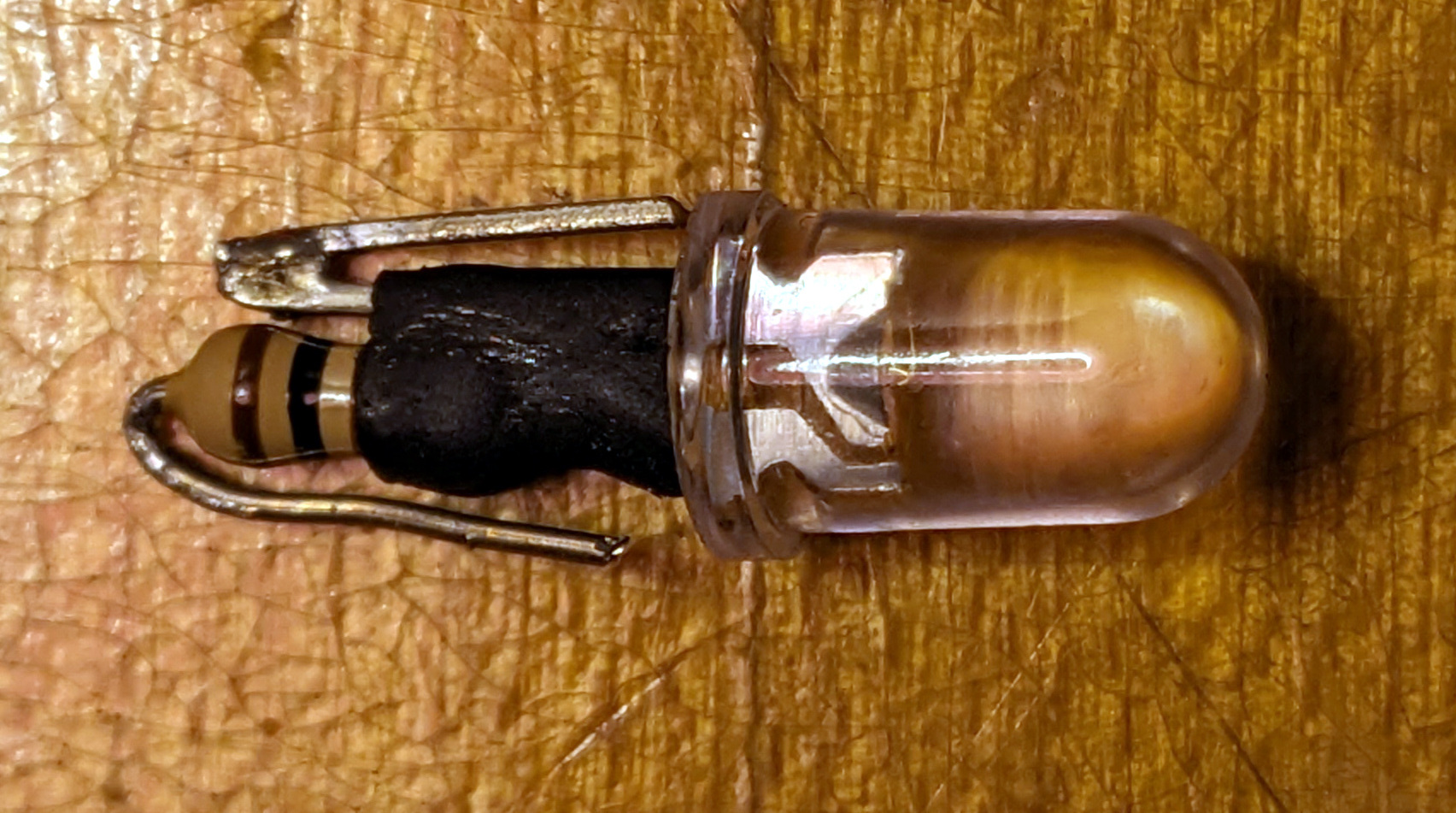
Other than writing the computer-side software to translate the RailDriver API information about air pressure into messages that could be sent over the CAN bus, I also wanted to make the gauge’s illumination work. It used to use incandescent bulbs, plugged into two sockets at the top of the plastic casing, and probably powered by a 24V supply. I wanted something better-suited to my 5V/12V supply that was more modern, so I created LED replacements for the incandescent bulbs. I also added a new module to my CAN controller firmware so that any module can easily include illumination (I’m calling it backlighting), and soon enough I could read my pressures in the dark:
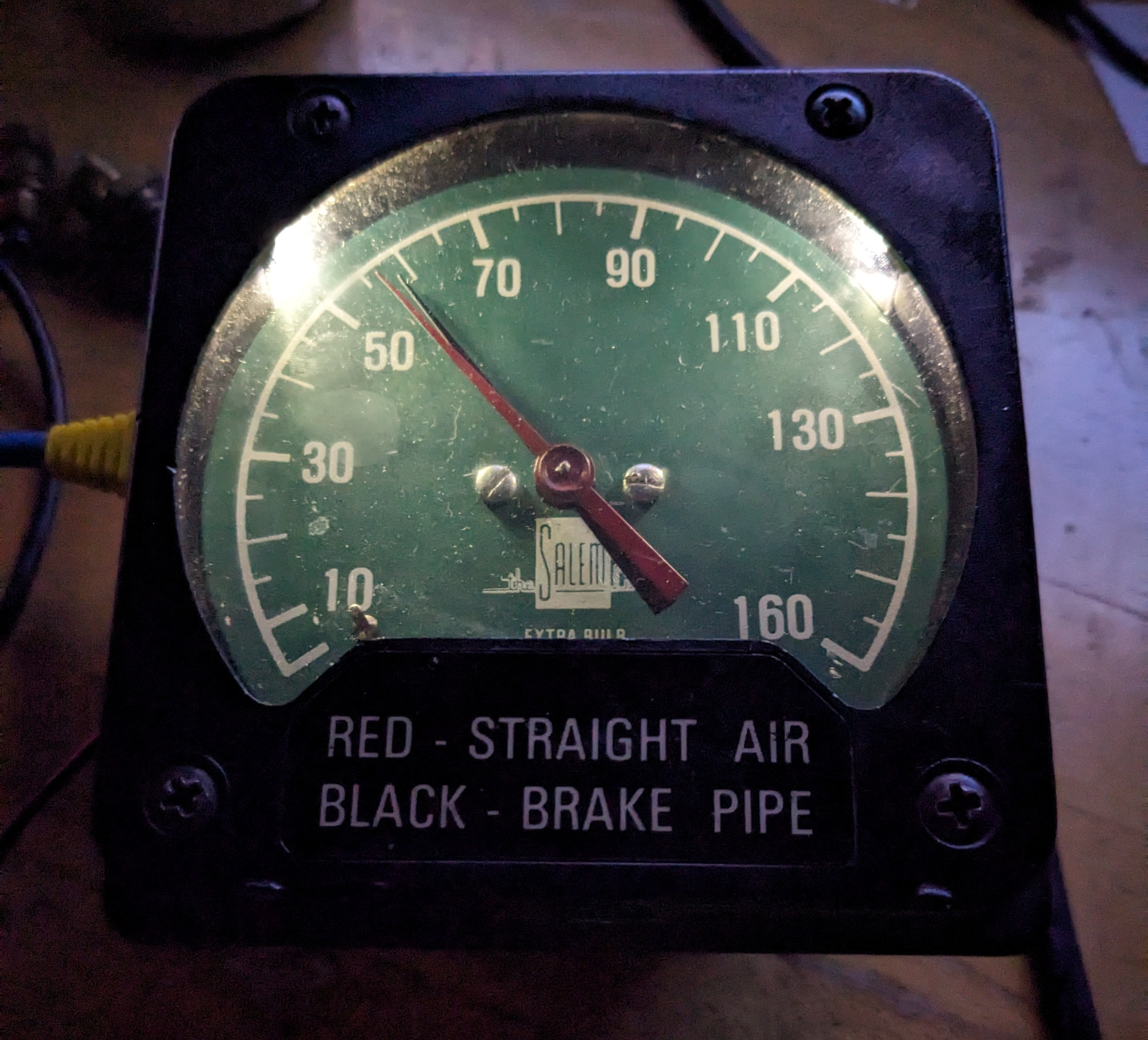
It was particularly gratifying seeing the illumination change as I turned the “Desk Illumination” knob on a virtual Class 802 train in Train Simulator:
Setting the air gauge illumination intensity from within Train Simulator
Finally, I can now see air pressure and AWS status, and I have buttons for AWS knowledgement and DRA (more on the DRA button in a future post). Other than DRA, coming soon are door controls and real UK train speedometers.