Train Simulator Controller: Stepper Speedometer Begins
For quite a few years now, I have been an avid Train Simulator player, operating virtual trains from the United States, the UK, and beyond. I’ve played Dovetail Games’ Train Simulator 2015 to 2022 and now “Train Simulator Classic”, FIFA-style annual upgrades that have incrementally improved the core game - and I’ve spent a decent amount of money on the much-memed Train Simulator DLC. The game is pretty immersive, but since part of my life also includes running real-life rail vehicles, I naturally want to make it feel even more real. The next logical step would be to build a physical controller for Train Simulator.
This has been done before: the best-known option is the RailDriver controller, a dashboard-esque plastic slab with most of the controls you’d need for a (virtual) train: independent and automatic brake levers, a combined throttle/dynamic brake lever, reverser, high/low horn lever, a digital speedometer, and a host of buttons that can be programmed and hand-labeled to be other train controls. While I have been intrigued by the RailDriver, the price has intimidated me ($200), and I also have mixed feelings about the plasticy, unrealistic look. I’m exploring inexpensive used RailDrivers to understand one of the options that is out there, but it’s not the only one.
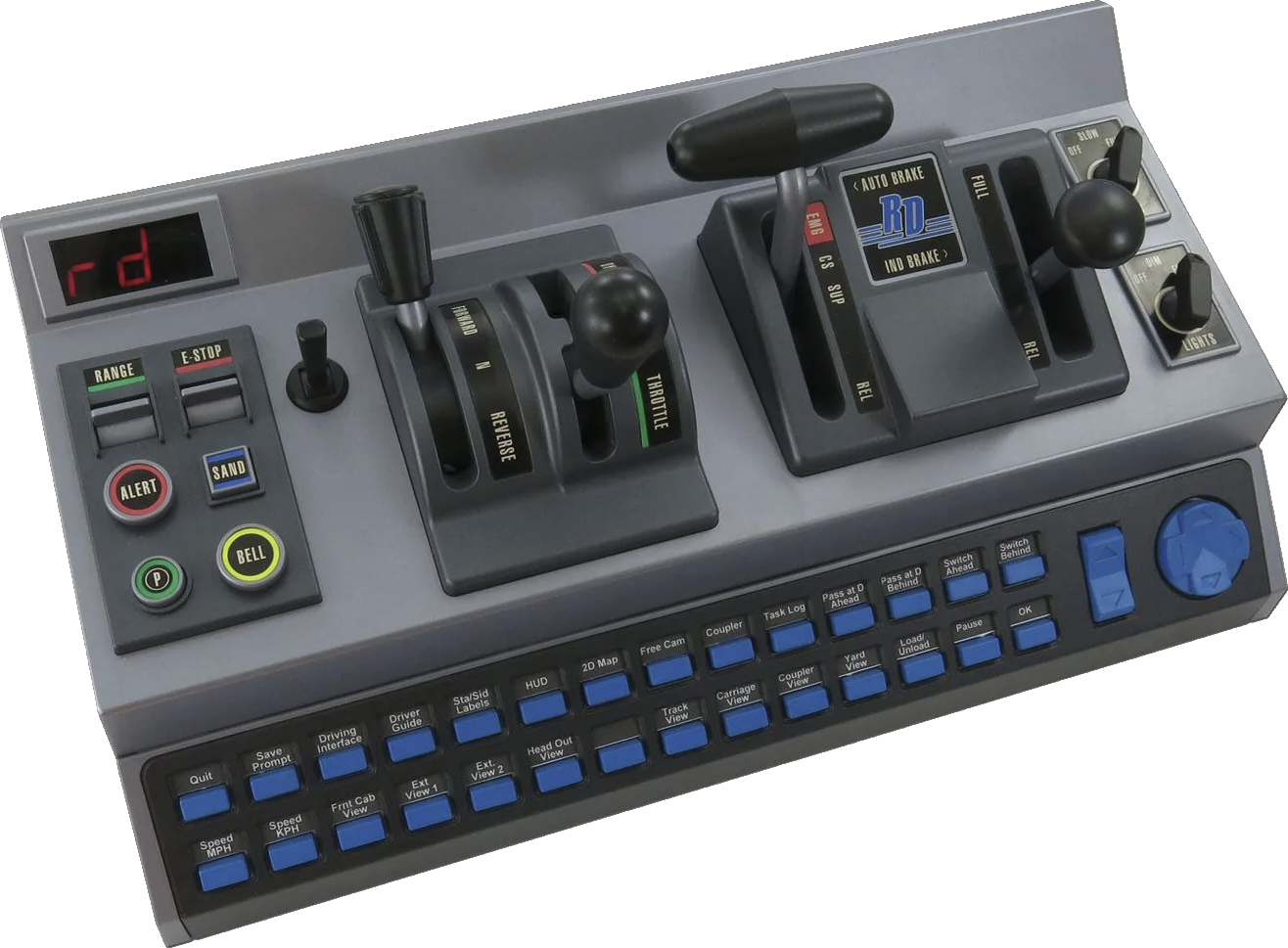 RailDriver Controller
More recently, Alan Thomson Simulation has released a set of pricey but sturdier, more realistic-looking controller components for Train Simulation, such as a door controller unit, a power/brake handle, and an AWS plunger. Each of these looks like a fine product, but each is also expensive, and most are sold out. What I really want is something that feels like the dashboard of a real train, and that’s the challenge I’m setting for myself.
Speedometer Prototype from a Tachometer
I arbitrarily picked the speedometer, the AWS alerter, and the door controls as the first pieces to tackle, as I anticipated these being primarily an electrical engineering and programming program, not so much a mechanical engineering problem. For the speedometer, I wanted to work with existing hardware, so scouring the internet, Amazon, and eBay, I discovered a tachometer that seemed like it would be a good base for the speedometer. It was backlit, the input power was +12V, the size was decent (I was generally shocked at the universal small sizes of any aftermarket automotive gauges I could find), and the price was good (about $22).
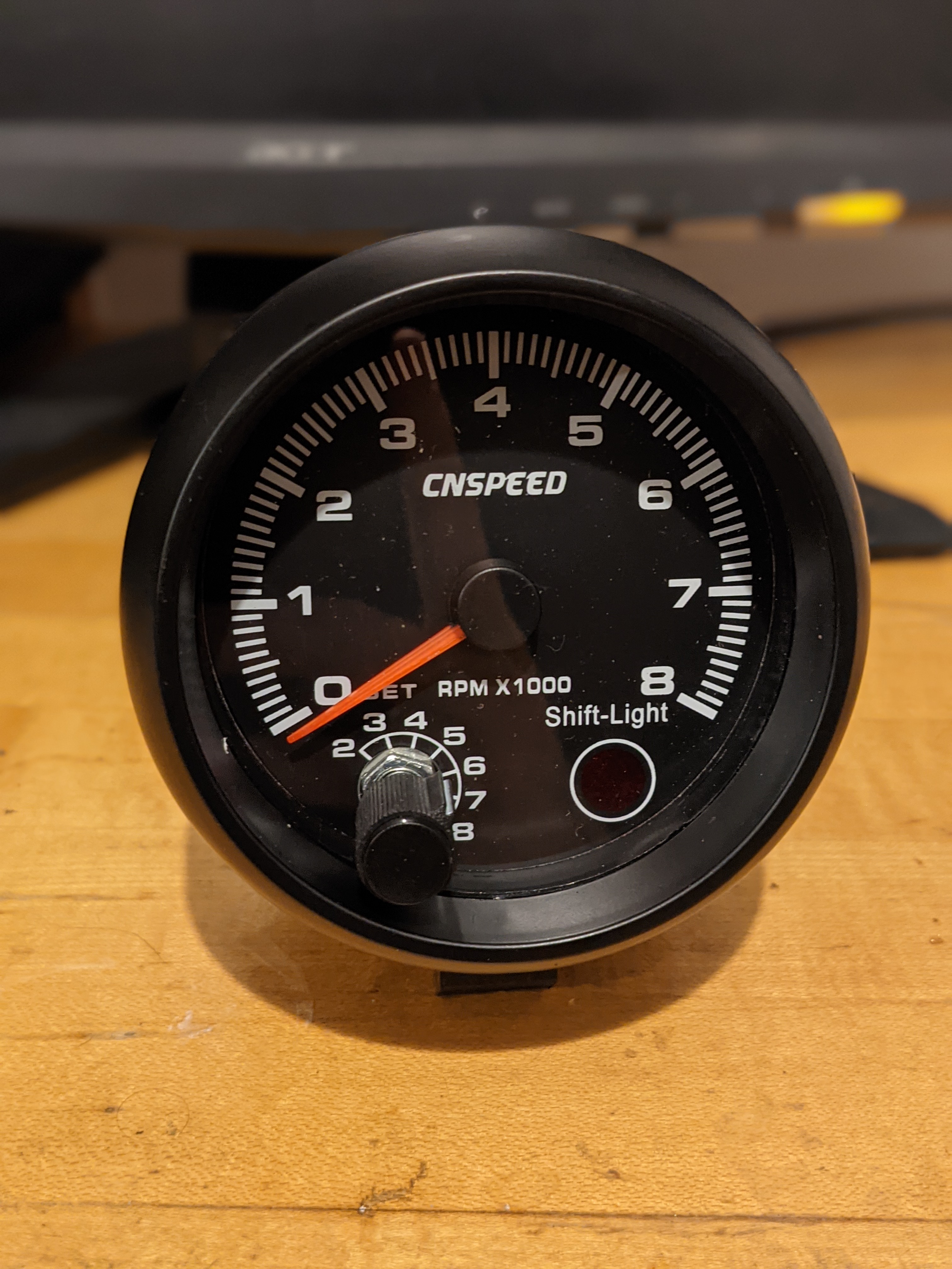 The tachometer on which I based the speedometer prototype
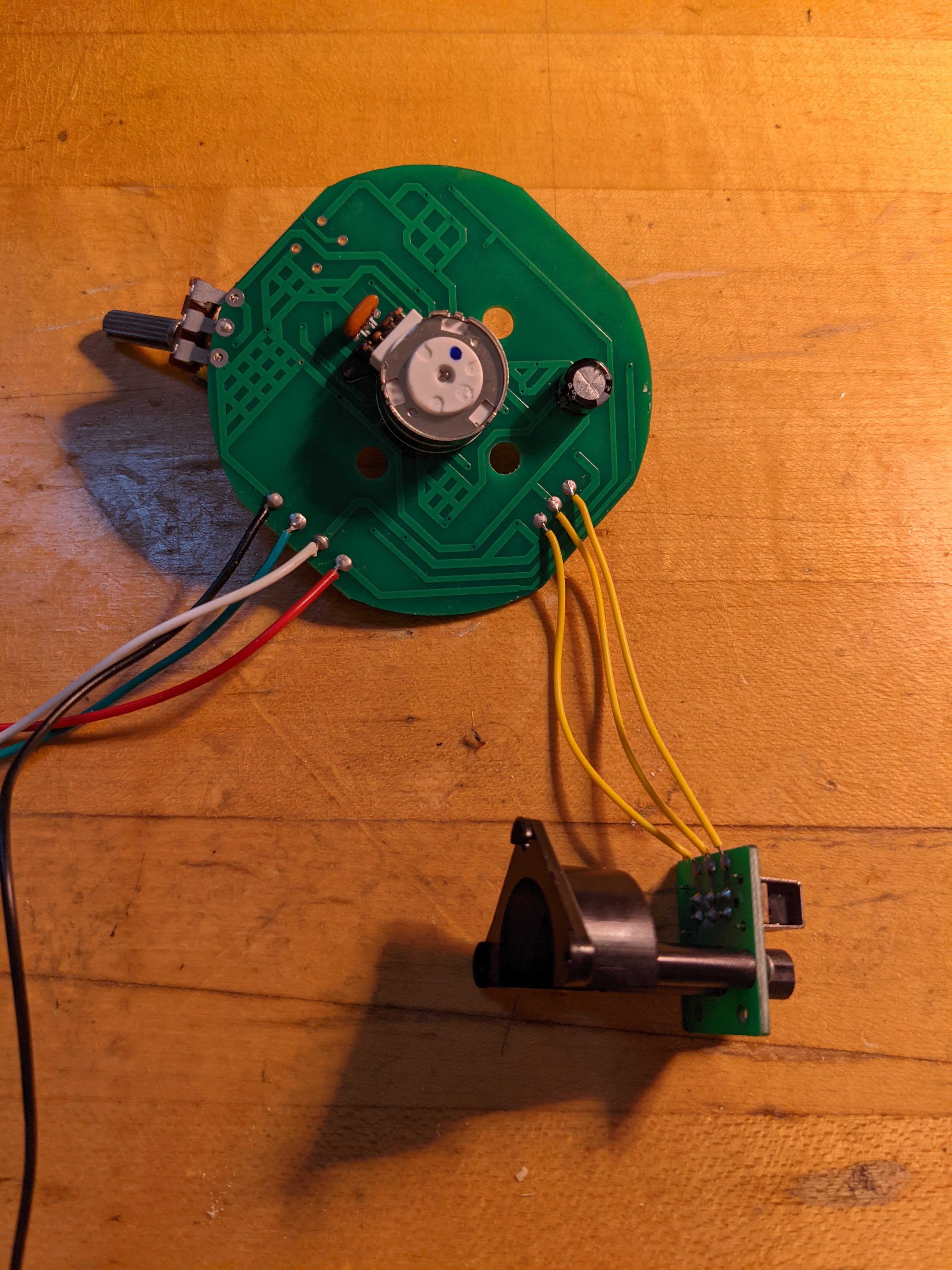
The next step was a teardown. Inside, I found a stepper motor, labeled PM20T-036, apparently a permanent magnet stepper motor made by NMB Technologies Corporation, with an OD of 20mm and nominally 36 steps per rotation (that would be 10 degrees per step). Experimentally, because in 36 full steps the stepper rotates through 288 degrees, it moves through 8 degrees per step. I actually got 280 degrees total for 36 steps, or 7.777 degrees per step, but this seems unlikely to be correct.
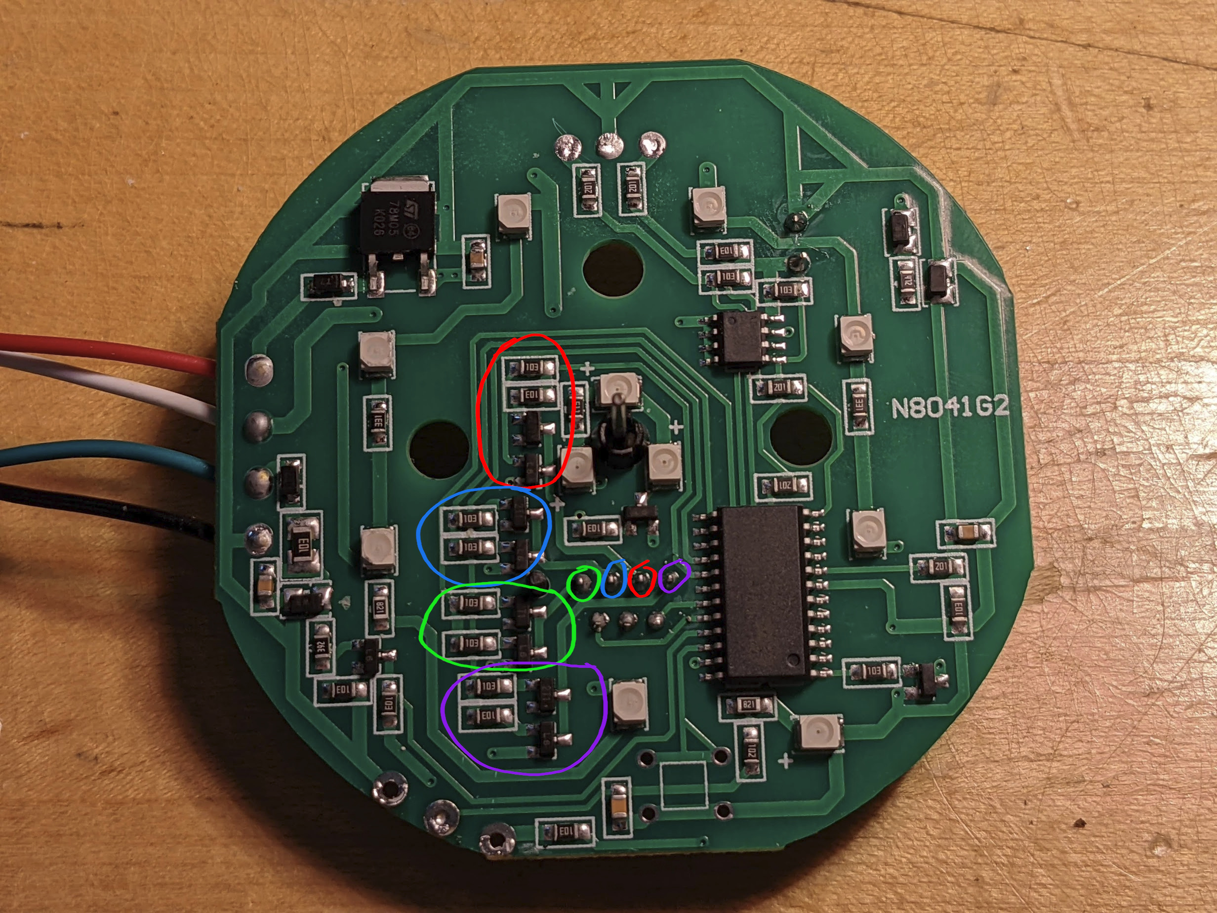
It’s a bipolar drive motor, and was linked via the expected 4 FET pairs forming two H-bridges to an EM78P418N microcontroller, a very simple 8-bit microcontroller with 52Kbit of ROM, 24 I/O pins, and relevantly to this application, 3 PWM generators. The original tachometer was designed to count ignition coil firings per second and move to the needle to the corresponding RPM on the gauge. I planned to use as much of the original hardware as possible, even extending to the microcontroller - but I soon determined that this wouldn’t be feasible, and later removing the microcontroller from the PCB. I did identify the four H-bridges, which stepper pin each connects to, and then which microcontroller pin each connects to.
I constructed my earliest prototypes with an Arduino, using its Stepper library to discover the correct wiring and stepping sequence for the stepper motor. For something with the granularity of a speedometer, though, I would need to use microstepping: we want the needle to at least be able to step with 1-mile-per-hour increments, and ideally even more finely (while covering a range of 0 to at least 150mph). The Arduino wouldn’t be powerful enough for this.
I chose the Raspberry Pi Pico as my controller for the stepper motor, both because it’s a cheap, powerful controller for all kinds of hardware and protocols, and because it gave me a good excuse to finally learn how to use the Pico. I started with a simple Pico stepping library that did not perform microstepping, and worked my way through the basics of creating Pico programs on Windows to integrate the microstepping solution suggested here on the Raspberry Pi forum.
This solution uses a single PIO program to PWM the two coils of the stepper motor together, including a “combined” phase where both coils are energized to try to minimize a downside of microstepping called “torque ripple”. Relevant to stepper applications where a nontrivial load is being moved, microstepping significantly reduces the available torque. However, the torque varies through the microsteps from one full step to another. At one full step, 100% of one coil is holding the rotor, and 0% of the other coil is active. Halfway through the microstepping sequence, when sine and cosine are (logically) used to choose the duty cycle of each coil, both are 70.7% active. I believe the torque ripple reduction feature of this PIO to be nice, but not vital for my application, since the tachometer needle weighs so little.
Choosing an AWS Acknowledge Button
I most often drive UK trains in Train Simulator, and UK trains have an Automated Warning System (AWS). This uses a sequence of permanent magnets and electromagnets mounted between the rails and coils underneath each train to warn the driver of impending speed restrictions, whether permanent or because a signal ahead is showing a restrictive aspect. The AWS system consists of a button, a buzzer, and a visual indicator colloquially called a “sunflower”. There’s an AWS sunflower on eBay for £400,so I may end up needing to make my own. The buzzer exists in Train Simulator’s audio, leaving the button as the most immediate need.
After a great deal of eBay searching, image searching, and general research, I found this excellent Allen Bradley 800T momentary button with a yellow mushroom. It requires quite a bit of force to press, it’s large, and it feels substantial. Hitting this button already feels so much more satisfying than pressing the Q key on my keyboard to acknowledge an AWS alert.
Putting It All Together
I used PyRailDriver to create a very simple PC-side program to communicate with the Pico through serial-over-USB according to the following protocol:
1 |
|
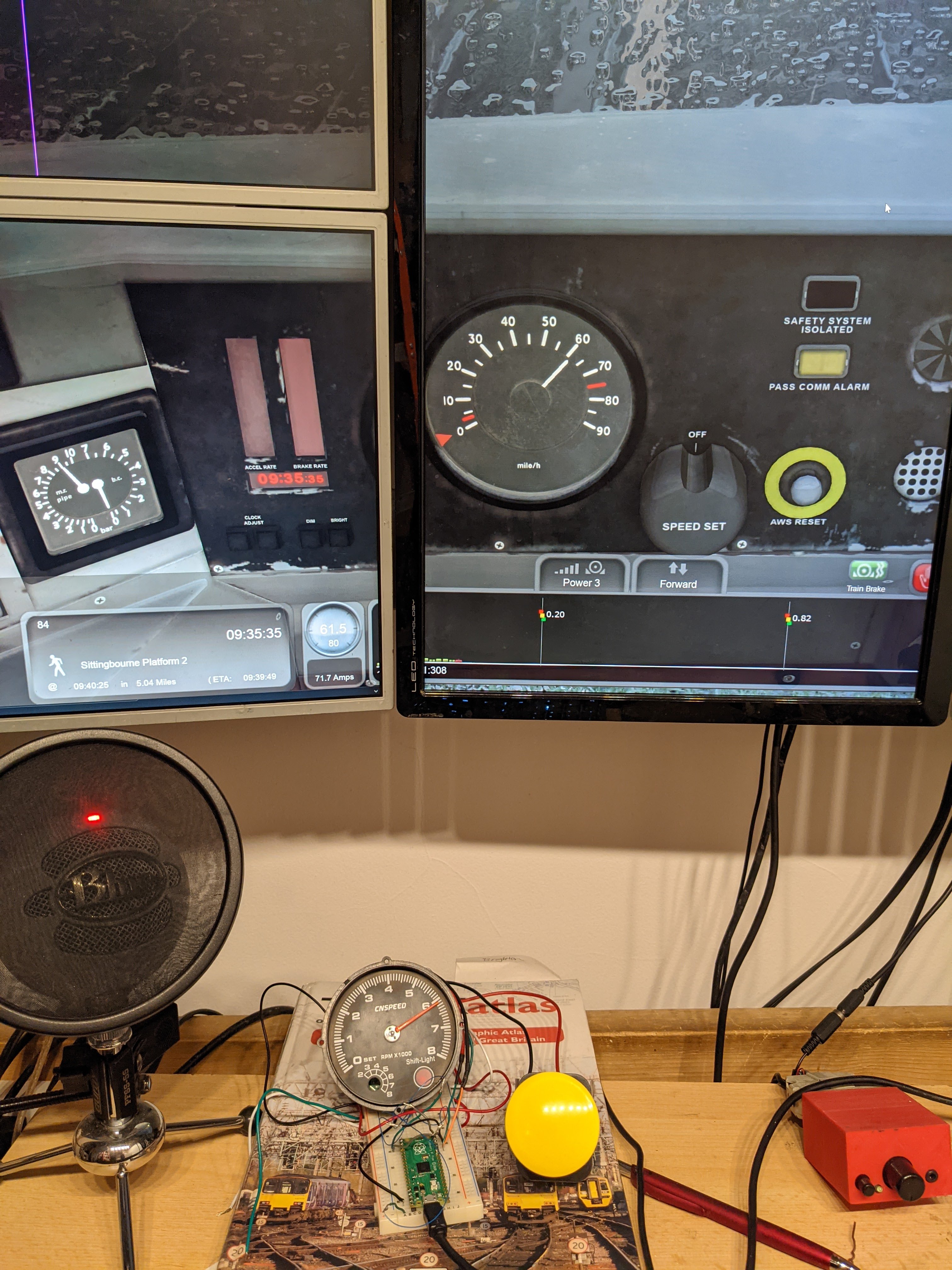
And I tried it out with Train Simulator! You can see from the photograph below that I calibrated the stepper to match the printed plastic insert from the original tachometer, where each digit is tens of miles per hour instead of thousands of RPM. It performed pretty well, with one notable exception: I find that the needle moves much further during the four microsteps closest to a full step, and much less far during the four microsteps at the middle of the range between two full steps. I have performed significant testing, down to measuring and charting current draw through a single coil with PWM duty cycle from 0% to 100% versus a theoretical current assuming a 5mA drop through the attached current limiting resistor. I recorded the needle position on the tachometer scale at successive microsteps: 7, 7.5, 8, 9.5, 10.5, 11, 11.5. That is, delta positions of 0.5, 0.5, 1.5, 1.0, 0.5, and 0.5, within measurement precision.
There are many next steps on this project, from figuring out how to fix this nonlinearity to looking into building an AWS sunflower to choosing buttons for the door controls, the latter task of which has already consumed significant research and time.