
Train Simulator Controller: CAN Controller, Part 2
I’m building a physical cab dashboard to control Train Simulator, from master controller to an AWS sunflower to an air gauge and speedometer, and everything in between. In a previous blog post, I detailed the CAN controller I have been designing to power every instrument and sensor in the system. In my Train Simulator setup, as in a real vehicle, using a CAN bus connecting semi-autonomous controllers provides fault tolerance and distributed computing that makes the system more robust. Each controller has a very specific task and needs little computational power, and any instrument can be added or removed on the fly. After the first few CAN controller versions detailed in that blog post, I had features to add and debugging to perform.
Version 0.7 of the CAN controller represented a major step forward from previous fabricated versions 0.3, 0.4, and 0.6:
- Version 0.3 was the base version of the board presented in the previous blog post.
- Version 0.4 added a Schottky diode between the Raspberry Pi Pico’s USB +5V input and the CAN controller board’s external +5V input, allowing both power supplies to be safely used.
- Version 0.6 added configuration pads, allowing the function of any board to be set without changing its firmware simply by bridges a set of solder pads. As will be discussed below, with 3 GPIO pins, I was able to get 27 possible configuration IDs.
- Version 0.7 finally fixed the overheating isolated DC power supply IC. It also added an extra higher-power FET, so that each controller can control up to three higher-current 5V or 12V devices, from a previous two.
In version 0.6, I added a set of solder pads to allow the function of the board to be set in hardware. Conceptually equivalent to DIP switches or
jumpers, these three triplets of solder pads can each be left unsoldered, soldered on one side, or soldered on the other side. I needed to detect as
many different IDs as possible with as few GPIO pins as possible, so each GPIO pin is connected to the middle of the triplet, and is floating. To
detect a floating pin, the Pi Pico tries pulling the pin down and reading it, then pulling it up and then reading it. If the pin’s state follows the
pull up/down, then it’s floating. On the other hand, the center pad can be bridged to its left or right, connecting it to ground or VCC, in which case
it doesn’t follow the pull up/down. This yields three potential states per GPIO pin, and 3^3=27 total IDs.
Version 0.7 solved the longstanding problem with the isolated DC power supply IC (UCC12040). Most of the time, this IC performed its intended function: taking the VCC on the Raspberry Pi side of the isolation gap, turning it into AC, transmitting it through a tiny transformer inside the AC, and then rectifying it back into regulated but isolated DC for the far side of the CAN bus transceiver. However, this IC would sometimes get hot, and CAN bus communication would cease. Not until I read more on how this IC worked did I realize what might be going wrong, and poring over the datasheet confirmed it: the pin to control the frequency of the oscillator generating AC for the transformer was floating, not pulled down as it needed to be when no external signal was being supplied. Together with some extra decoupling capacitors, the overheating behavior and the CAN bus communication interruption both disappeared: my supported hypothesis is that the oscillator inside the IC was erroneously being disabled, leading to DC being pushed through the transformer, dissipatinng the power as heat instead of transmitting it, and thus also preventing the far side of the CAN transceiver from being powered.
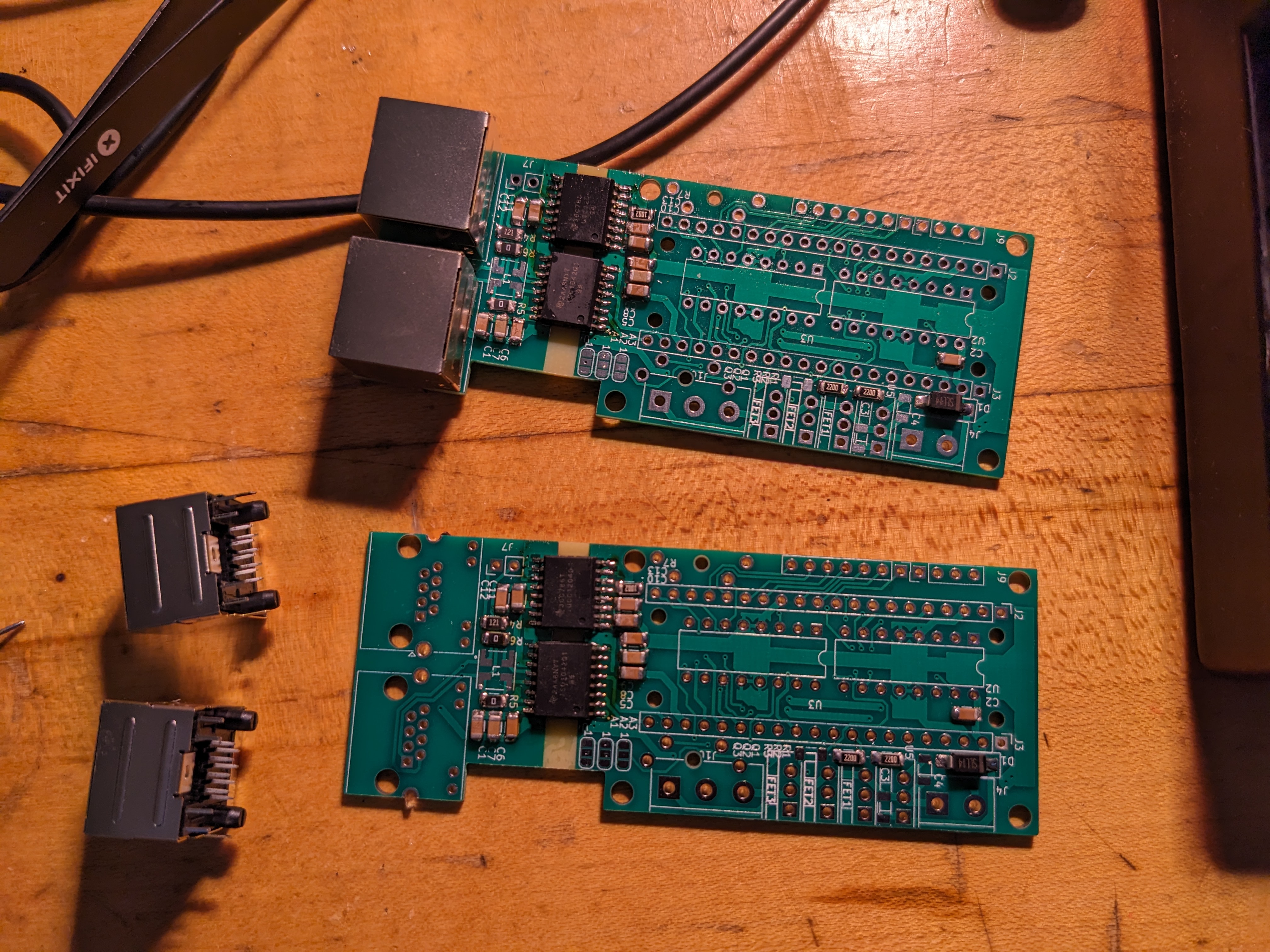
 Several v0.3 boards populated and used for testing
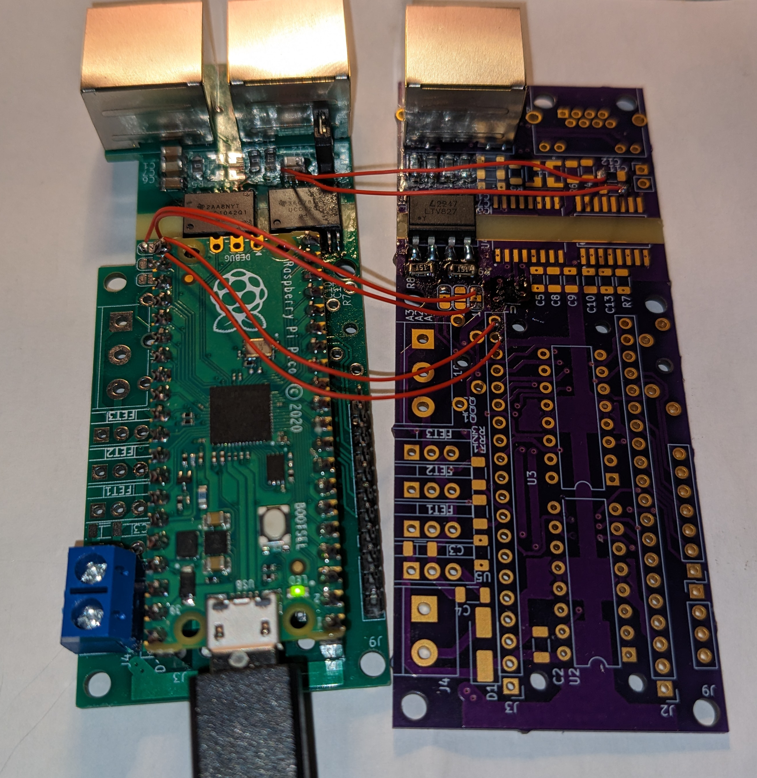
Version 0.8 brings a new feature spurred by the vagaries of browsing inexpensive RJ-45 jacks on Digikey. I happened to select a jack that includes green and yellow LEDs, typically used to show that a link has been established (green) and that communication is occurring (yellow) when used for Ethernet. I decided that I should make these LEDs show CAN bus activity, and in the spirit of maintaining correct isolation across the isolation gap in my CAN controller, I chose the LTV827 optoisolator for the job. The ISO1042 is active-low, though, and I wanted my LEDs to light up when activity occurs, so to avoid expanding the size of my controller board any further, I snuck a tiny TSOP-6 dual inverter on the “near” or Pi Pico side of the controller, ensuring I would only be sending a signal through the optoisolator when the CAN RX or CAN TX lines on the Pi Pico went low. Using the isolated VCC on the far side, as supplied by the now-reliable UCC12040, I got a flash of green and yellow whenever a successful CAN bus packet is sent.
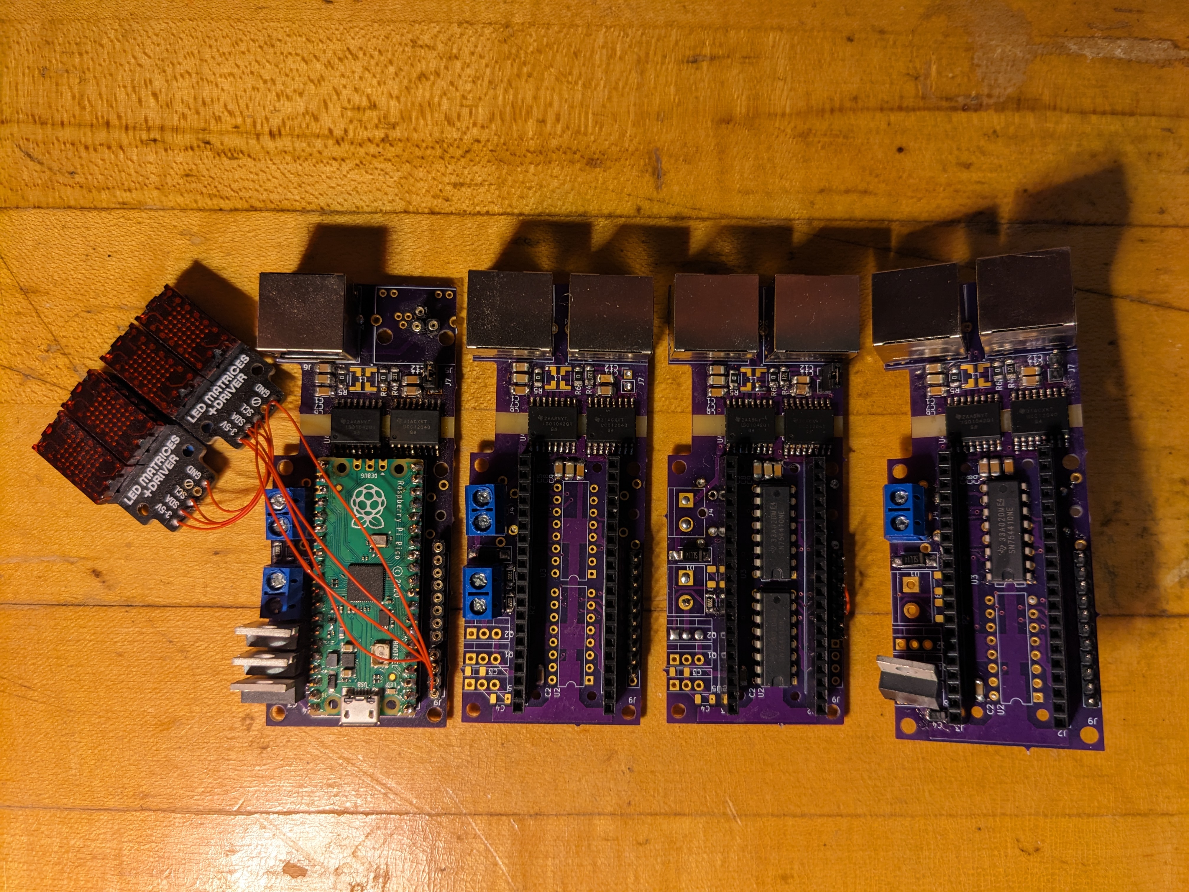
 CAN activity LED testbed, populating only the LED components on a new board
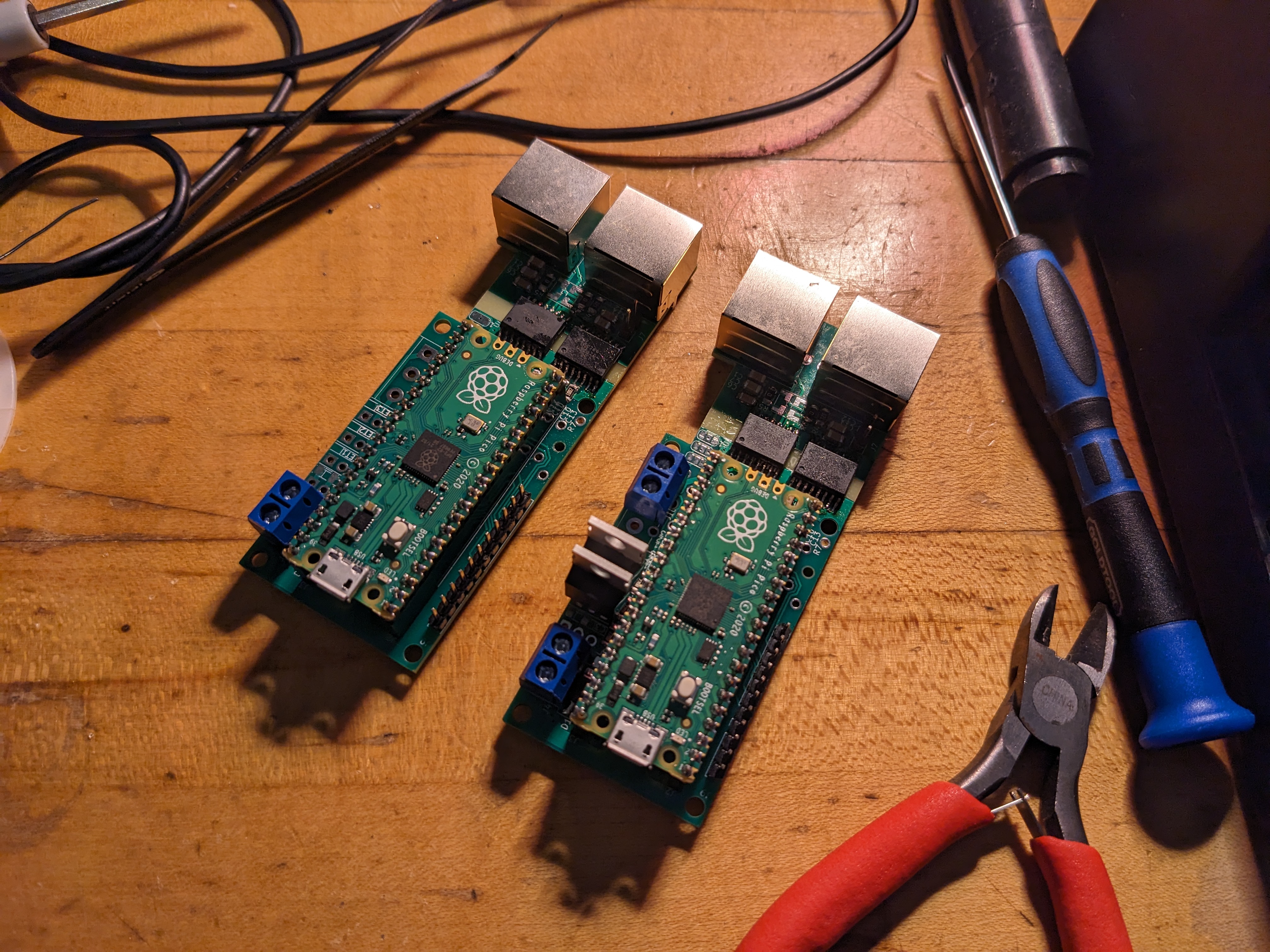
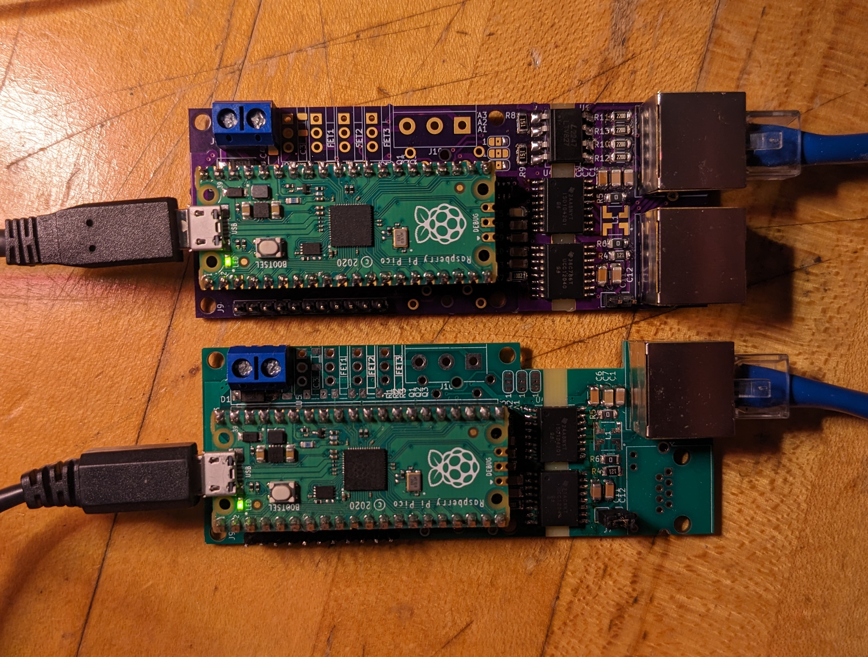 Completed board under test
This turns out to actually be a helpful debugging tool: when something on the bus prevents a packet from being correctly acknowledged by any of the other CAN transceivers on the bus, the sender will immediately re-send it, leading to a solid green and yellow LED. I also encountered a firmware bug where my AWS/DSD controller (more on DSD in a future post) was sending updates far too frequently, also obvious from these activity LEDs.
CAN bus activity LEDs in action
Next time, I finally get a real UK train speedometer connected, the instrument that I started this project with!