
Train Simulator Controller: CAN Controller, Part 1
I’m building a physical cab dashboard to control Train Simulator, from master controller to an AWS sunflower to a speedometer, and everything in between. The engineer or hobbyist interested in getting this project ready expediently would probably find their favorite microcontroller, figure out how to interface enough GPIO pins to it (maybe an Arduino Mega?), and connect all their hardware to that microcontroller. Not me.
Ever dedicated to over diligently engineering my projects, I decided to build each component of my Train Simulator setup with a
controller capable of speaking connecting to a CAN bus. This would allow me to build truly modular components that could be arbitrary added and
removed, and there’s another method to my madness: the possibility of one day being able to control an actual train with my Train Simulator setup.
For the immediate future, I set out to design a CAN controller board that would provide all the different interfaces I would need for my various
controls and instruments, would be easily programmable, and would provide at least some of the safety features of a real CAN bus transceiver,
including proper isolation.
I began by enumerating the different interfaces I would need, based on the different types of controls and instruments I planned. I envisioned that each instrument or set of related controls would have its own CAN controller board. For all sorts of rotating instruments, like speedometers and air gauges, I anticipated needing to be able to control up to two stepper motors each. I would need an array of simple inputs for buttons like door controls (at least 5 pushbuttons or non-rotation-sensor inputs on a master controller, by my count). I’d want a rotation (angular position) sensor for lever controls like my master controller and any future brake stand. I would want an I2C interface with moderate 3.3V current for items like a dot matrix display (read onwards…). And I needed high-current outputs, capable of operating at 5V or 12V (or even higher), for items such as my AWS sunflower, instrument backlights, and illuminated pushbuttons
And what about the brains behind the operation? Having recently worked a bit with the Raspberry Pi Pico and the powerful RP2040 at its core when I performed my speedometer experiments, and having discovered Kevin O’Connor’s CAN2040 library, I selected the Raspbery Pi Pico as my microcontroller of choice. Here’s how I designed the board to work:
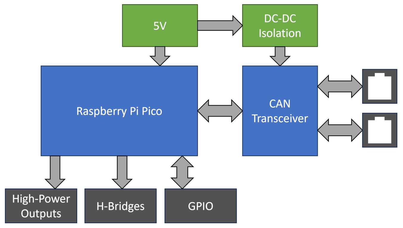
The Pi Pico is powered by a 5V supply (USB or a 5V bus), and directly interfaces with hardware through its GPIO lines, including where relevant via FETs to provide high-voltage and/or high-current control. Following proper CAN bus principles, the power supply for the CAN side of the CAN transceiver is provided by an isolated DC-DC power supply, and the Pico can then communicate via an isolated CAN bus with other CAN transceivers (namely others of this controller board). In addition, one of these boards is designed to be used as a bridge communicating with the computer running Train Simulator (e.g. over USB) and translating messages to and from the computer off of and onto the CAN bus.
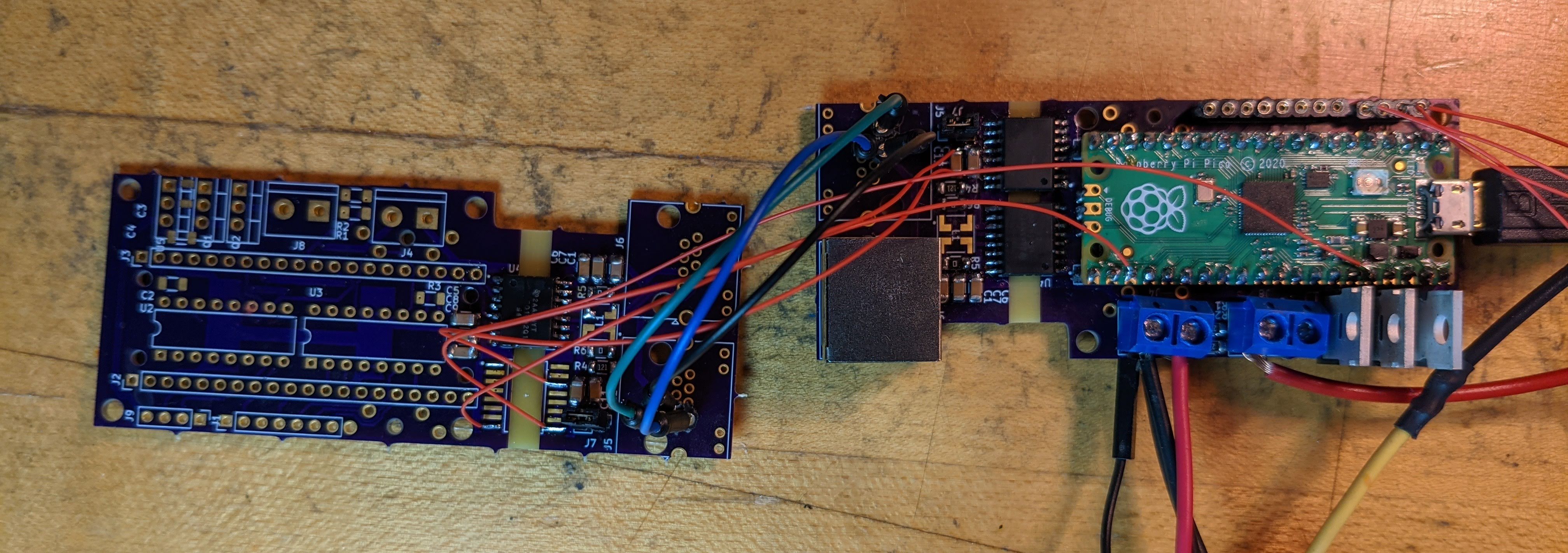
A few days in KiCad and a bit longer for Digikey and OSHPark deliveries, I was ready to populate and test version 0.3 of my CAN transceiver.
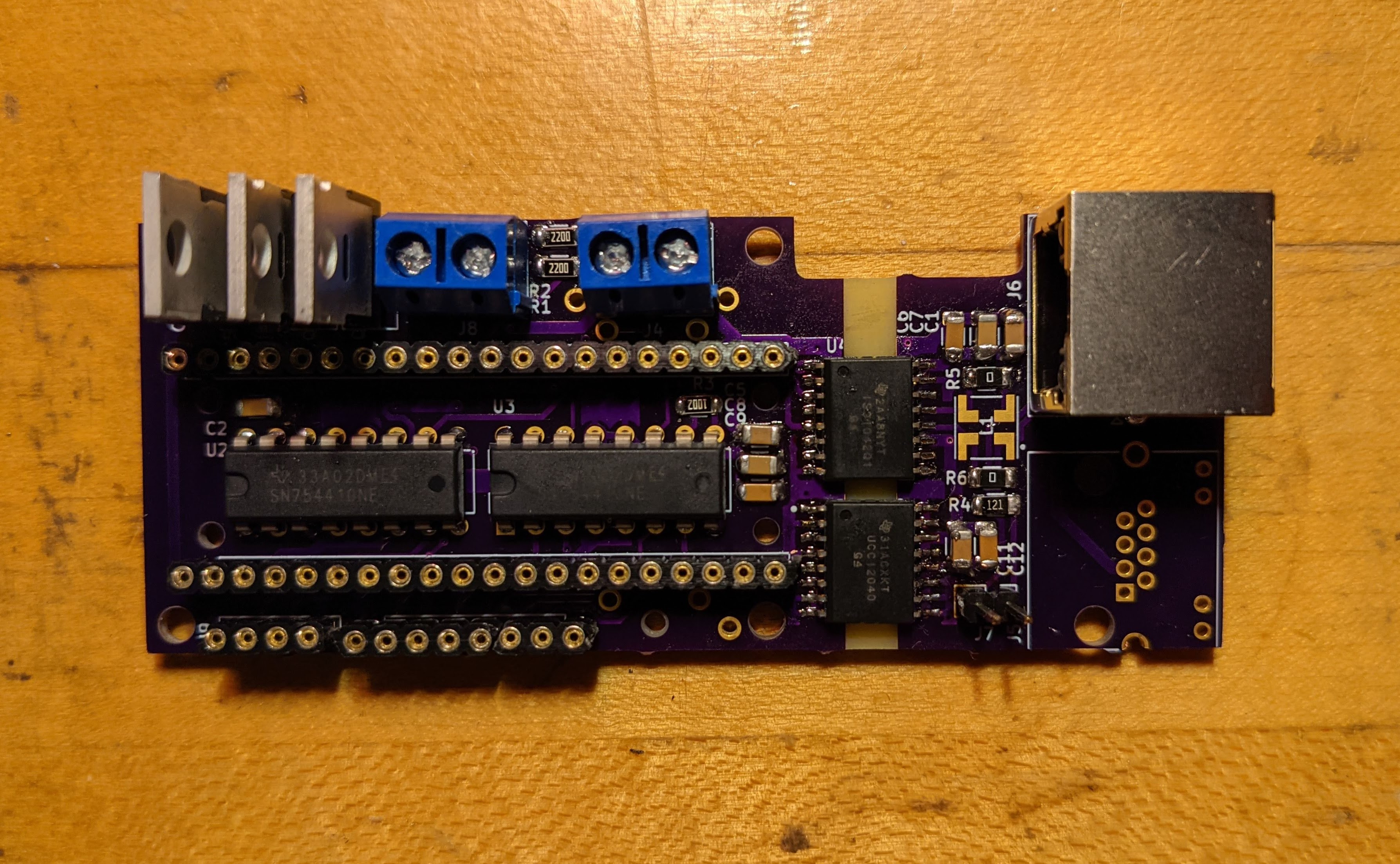
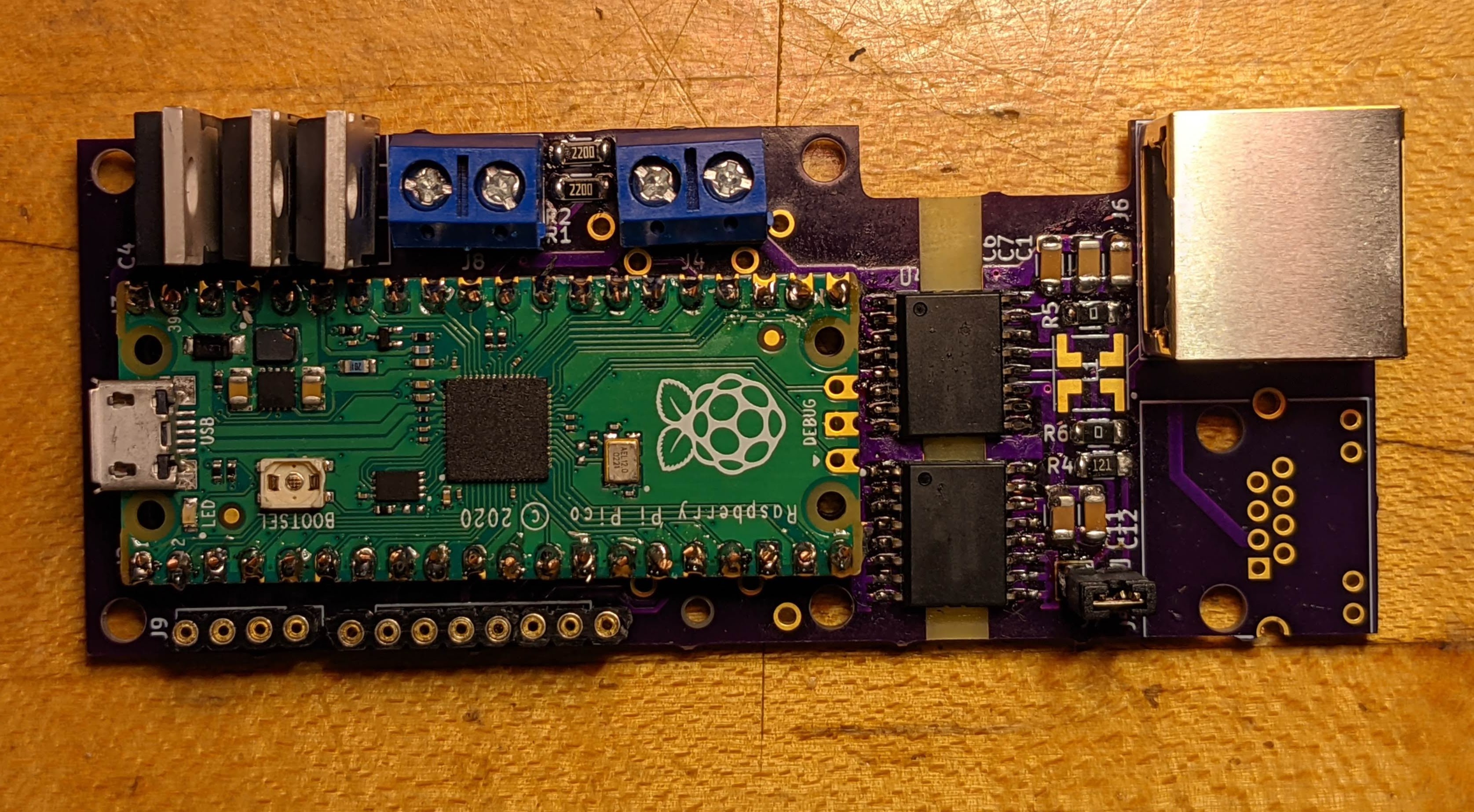
You may have guessed from “version 0.3” that this wasn’t the very first board version, and I expected it to not be the last, either. Like most electronics projects, it evolved as I discovered both additional features and optimizations that could be added, and problems that could be fixed. Versions 0.1 and 0.2 of the board never made it to the fab, but v0.3 was promising. I used it as a testbed for three aspects of the CAN controller: powering and interfacing with the Raspberry Pi Pico, controlling hardware like my AWS sunflower and LED matrices, and of course the CAN interface itself.
First, testing its ability to control higher current/voltage hardware, like the 12V coils in the AWS sunflower. This simple Pico program periodically switches the state of the AWS sunflower by alternately triggering the set and reset coils:
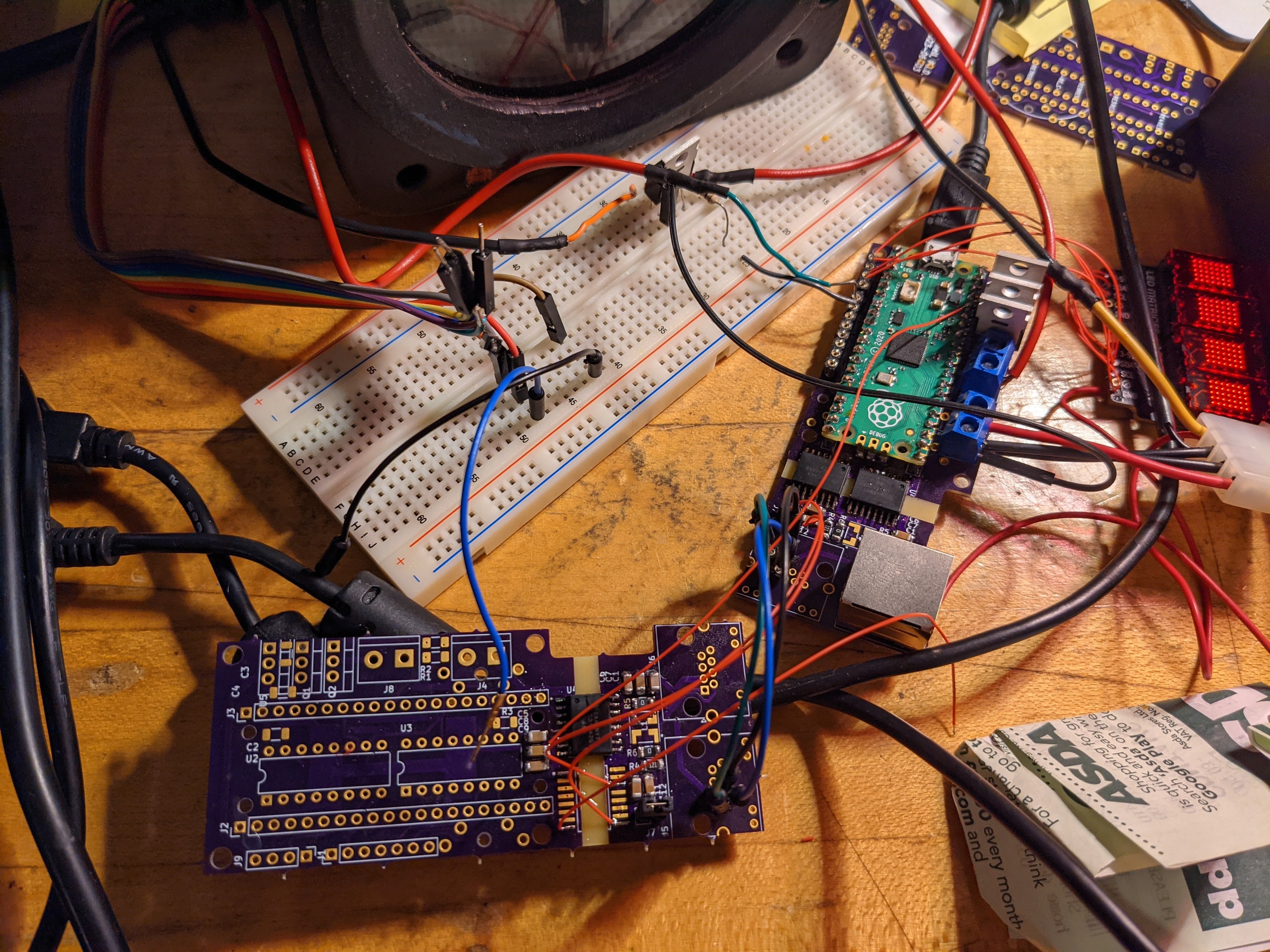
Second, testing its ability to interface with a computer and drive a pair of LED matrices, using an extra 3.3V regulator on the controller board. This test brings Train Simulator Classic into the fold, transmitting the current speed of a train as it accelerates out of Orpington, and additionally indicating whether the train is accelerating or decelerating.
A primitive test of the CAN controller board, ignoring its CAN capabilities. Instead, the board is receiving speed information from a Python program interpreting RailDriver API information, as in my first speedometer prototype, and displaying both the speed and the speed trend (accelerating or decelerating) on an LED matrix. This speed display was inspired by the Class 395 “Javelin” high-speed train.
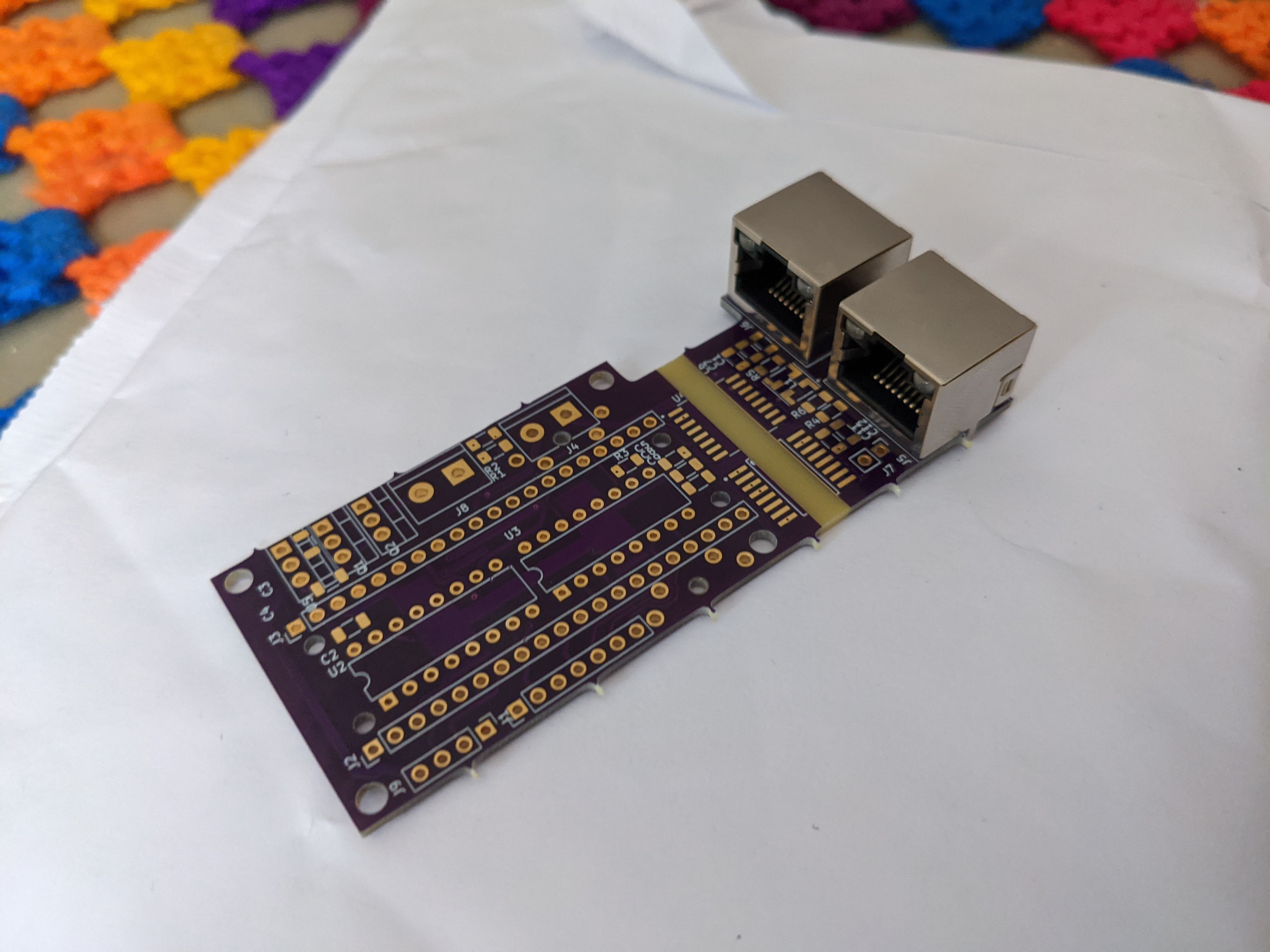
Finally, testing CAN communication. The CAN bus transceiver IC (ISO1042), DC-DC converter (UCC12040), and other components are sufficiently expensive that I undertook a simple test populating only the CAN transceiver of a second controller PCB with its support passives, using the power supply from the “host” board and even directly connecting the differential CAN bus lines instead of installing RJ-45 sockets (especially since the sockets ended up facing backwards on this first fabricated board version!).
I was pleased to find that CAN messages were successfully sent and received. A few firmware bugs in CAN communication were fixed. While I noted what appeared to be a Heisenbug on the hardware side, where communication would stop and occasionally the DC-DC isolated converter would become extremely warm, it took until v0.7 for the source of this rare problem to be identified and repaired.
And with that, I had a first functioning prototype of the CAN transceiver that will underpin every instrument and control in the final product! Future updates will detail the evolution and integration of this controller.