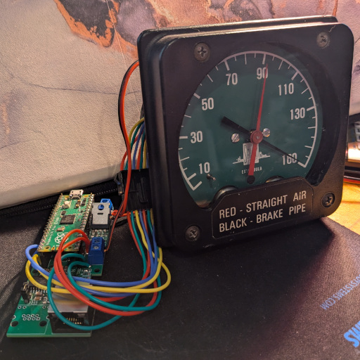
In my ongoing quest to build a physical cab dashboard to control Train Simulator, an important set of components are the gauges that tell me what’s going on with the train. As I build the dashboard into which to embed my gauges, I realized I needed to better modularize my air pressure gauge, moving the control circuit board outside the gauge. Here’s how I did it.
Having sporadically built controls and gauges to interface with Train Simulator over the course of a year, in April 2024 I began to figure out how to design the dashboard they would all fit into.
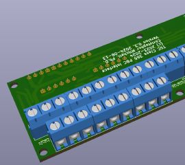
The core of a train simulator setup could be considered its throttle and brake. Having figured out how to interface a real UK Class 365 power/brake controller with Train Simulator, I designed and built a polished PCB to connect it to my Train Simulator setup.
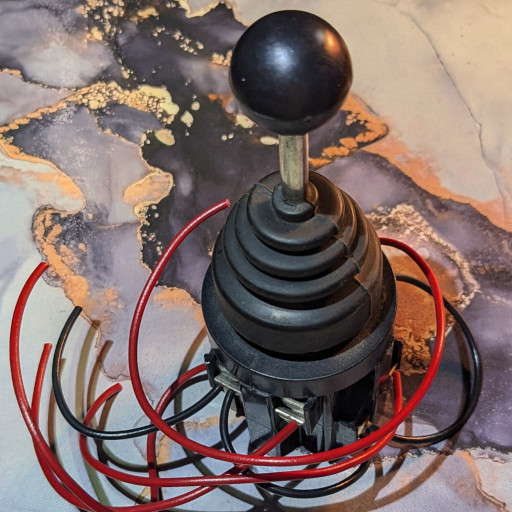
The core of a train simulator setup could be considered its throttle and brake. Having lugged a combined throttle/brake from a real UK Class 365 passenger train home, I reverse-engineered how it worked, then figured out how to interface it with Train Simulator.
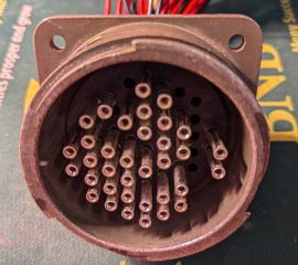
The core of a train simulator setup could be considered its throttle and brake, the control or controls that make a train go and stop. In previous blog posts, I detailed my exploration of building my own controller from scratch, but a fortuitous eBay listing provided me a real Power/Brake Controller (PBC) from a UK Class 365 train. Here’s how I got it home and reassembled.
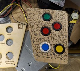
As the different pieces of my Train Simulator controller come together, a bite-sized first task of building the physical dashboard is the door controls placed at each side of the cab. Here, I detail the process of prototyping the door control panel from a Class 80x out of cardboard and the authentic buttons used in the real train, then laser-cutting refined prototypes I can use with my existing setup
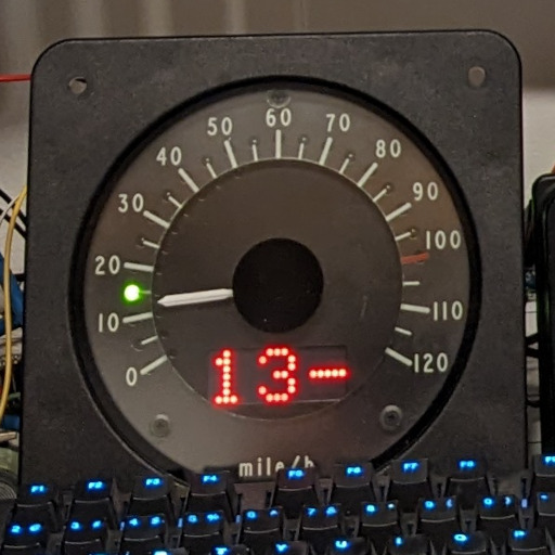
As I add more instruments to my realistic physical dashboard for Train Simulator, I have prioritized a speedometer, one of the most vital tools a driver/engineer uses to safely operate a train. After purchasing working, ATP-enabled speedometers, I set about determining how to build controller hardware and software to use the ATP features and the analog needle with Train Simulator to continue to enhance the realism.
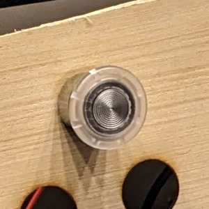
I’m building a physical cab dashboard to control Train Simulator, replicating the controls present in UK trains such as the Class 80x. One of the important safety systems is the Driver’s Reminder Appliance (DRA) that helps the driver avoid passing a red signal. I added a realistic DRA button to my Train Simulator dashboard, and here’s how.
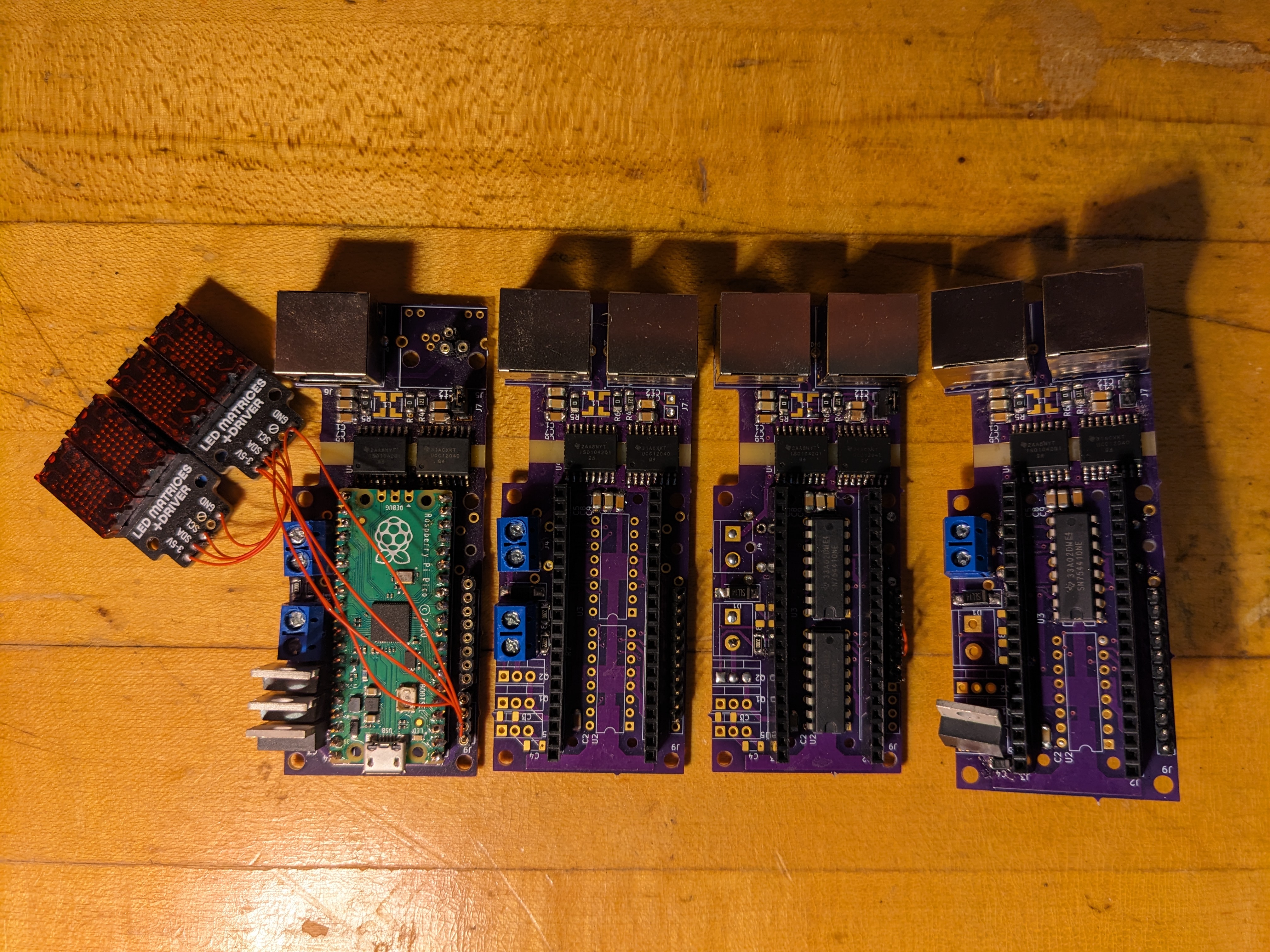
I’m building a physical cab dashboard to control Train Simulator, and to tie it all together as robustly as possible, I am use CAN. This protocol is designed to rapidly share small updates around a network in an electrically noise environment, and in a previous post, I detailed my first CAN controller designs. Here, I show the maturation of the CAN controller to solve bugs and make it useful for any control or instrument I add.
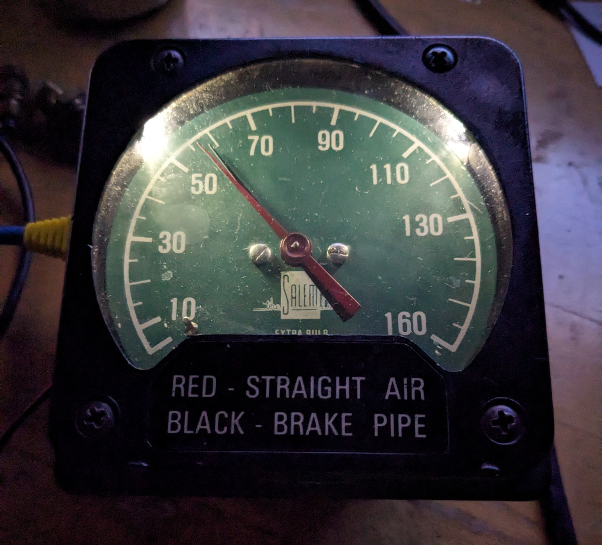
In my ongoing quest to build a physical cab dashboard to control Train Simulator, an important set of components are the gauges that tell me what’s going on with the train. I already showed off the internals of an AWS sunflower and early experiments with a speedometer. In this post, I show how I turned a real, air-driven air pressure gauge into an electronic, CAN-bus-connected version for Train Simulator.
I’m building a physical cab dashboard to control Train Simulator, from master controller to an AWS sunflower to a speedometer, and everything in between. The engineer or hobbyist interested in getting this project ready expediently would probably find their favorite microcontroller, figure out how to interface enough GPIO pins to it (maybe an Arduino Mega?), and connect all their hardware to that microcontroller. Not me.
Ever dedicated to over diligently engineering my projects, I decided to build each component of my Train Simulator setup with a controller capable of speaking connecting to a CAN bus.