Train Simulator Controller: Power/Brake Controller, Part 1
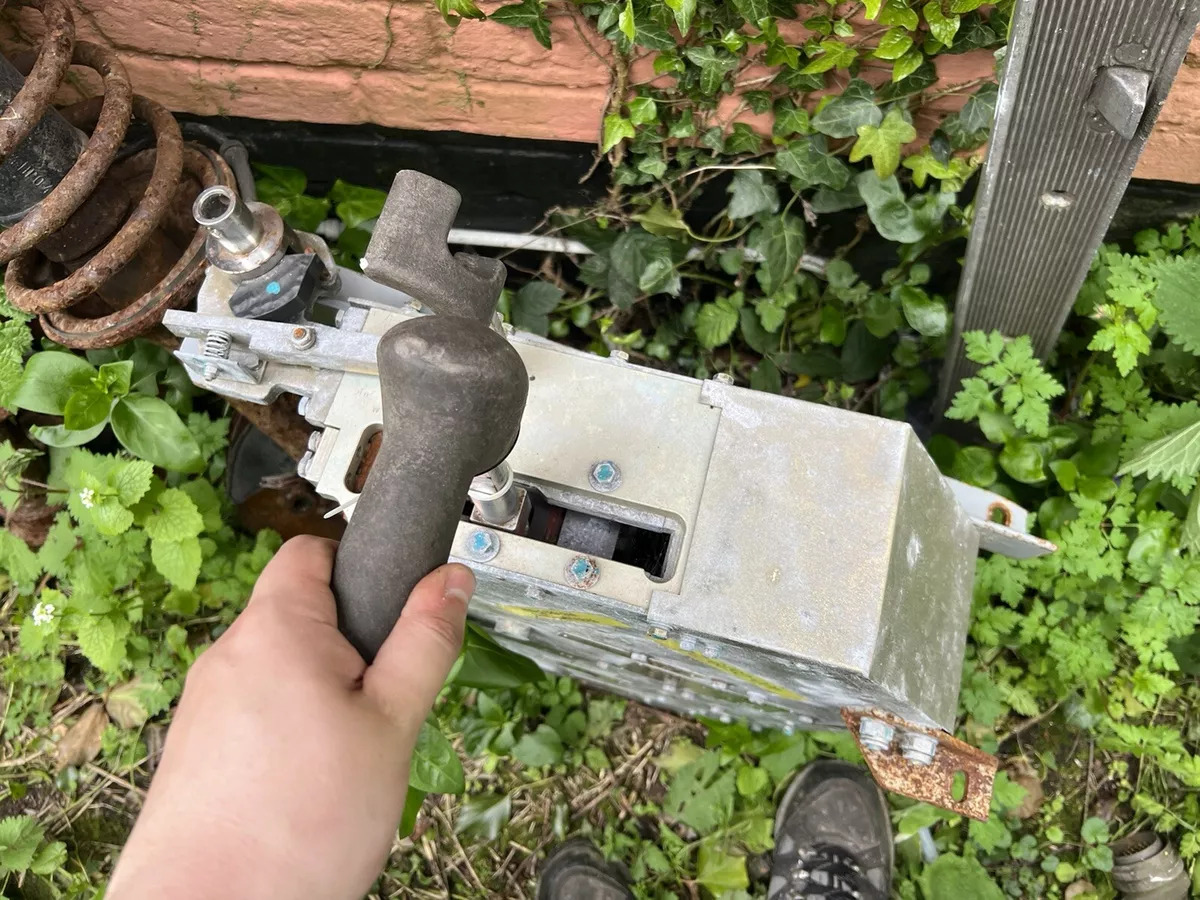
Among my very first steps in building a train simulation rig was exploring building my own throttle from scratch . I eventually built a full-scale prototype of a combined throttle/brake, but it was clear I would need to do significant engineering and machining before it was ready for prime-time. I was thrilled to therefore discover a real power/brake controller from a UK Class 365 train on eBay in May 2024. I of course jumped at it immediately, and didn’t have too much competition to buy this hefty, 70lb (32kg) chunk of metal, wires, and switches. The seller was nice enough to drop it off at the home of a very patient fiancée, and behold, this major component of my future train simulation rig was mine.
This Power/Brake Controller (PBC) lets you control the direction of the train via a control called the reverser, and the speed of the train with a combined power/brake handle. The available power/brake handle notches are:
- Emergency Brake
- Brake 3 - Brake 1
- Off
- Power 1 - Power 4
This is enough for most of the EMU passenger trains that I want to simulate in Train Simulator, although it will fall short for trains with separate power and brake handles, trains with brake handles that can be arbitrarily set to any position, and trains with more than 3 brake notches or more than 4 power notches. This should work fairly well for the Class 80x trains (Class 800, Class 801, Class 802, etc.) that I particularly want to simulate, which have 4 power notches, 3 brake notches, and an emergency setting. This Class 365 controller also has a neat feature that I haven’t seen in a lot of passenger trains: a red “brake holdover” button sticking out of the power handle, which when depressed will keep one notch of brake engaged even when off or in a power notch. This serves two purposes in the real trains: allowing hill starts without rolling back, and controlling wheel slip while accelerating on slippery rails. It remains to be seen if I will be able to convince Train Simulator to understand power and brake applied simultaneously on any of the relevant passenger trains.
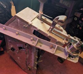
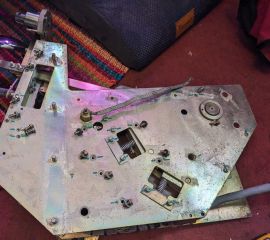
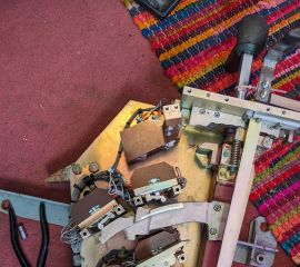
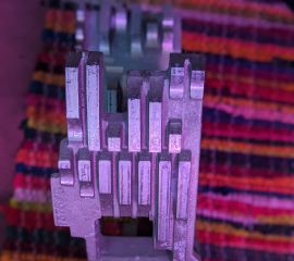
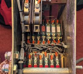
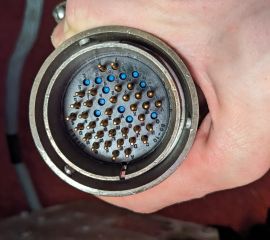
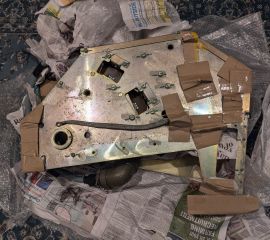
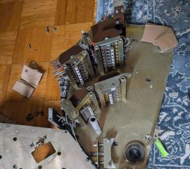
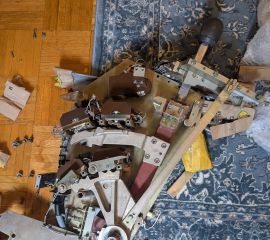
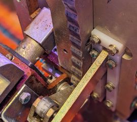
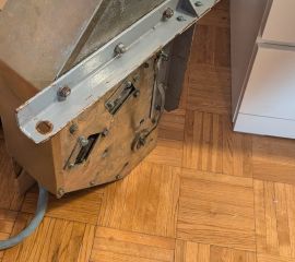
In order to ship it from the United Kingdom to the United States, I needed to disassemble this unwieldy component into lighter and smaller pieces. Thus began a carefully photographed and documented disassembly process: I removed two long arms, one for the reverser handle and one for the power/brake handle, each of which has a large metal plate with patterns to actuate roller lever switches. Four banks of these roller lever switches were wired together into a substantial cable bundle leading to a circular 48-pin, environment-sealed milspec conector. Switches for the emergency brake and brake holdover switch are also inside. Heavy metal covers wrap the whole PBC unit, fastened with a variety of metric hardware. As I incrementally disassembled the PBC, here are some of the photos I captured:
Here’s how it works: as you move the two handles backwards and forwards, the projections and grooves on the metal plates either depress or release the rollers on the roller lever switches. There’s a power switch that when in the “off” position physically prevents the reverser handle from moving out of the “Off” position to the “Forward”, “Neutral”, or “Reverse” positions. And when the reverser handle is in the “Off” or “Neutral” position, it in turn prevents the power handle from going into any of the 4 power notches.
After this disassembly and careful padding and packing, the bits of the PBC were ready to travel from the UK to America. And once they arrived, I repeated the process in reverse, following my photos and notes to reassemble the PBC. Shortly thereafter, I prototyped a circuit to connect it into my Train Simulator setup and successfully tested this, coming soon in the next blog post!

