
Train Simulator Controller: July 2026 Progress Roundup
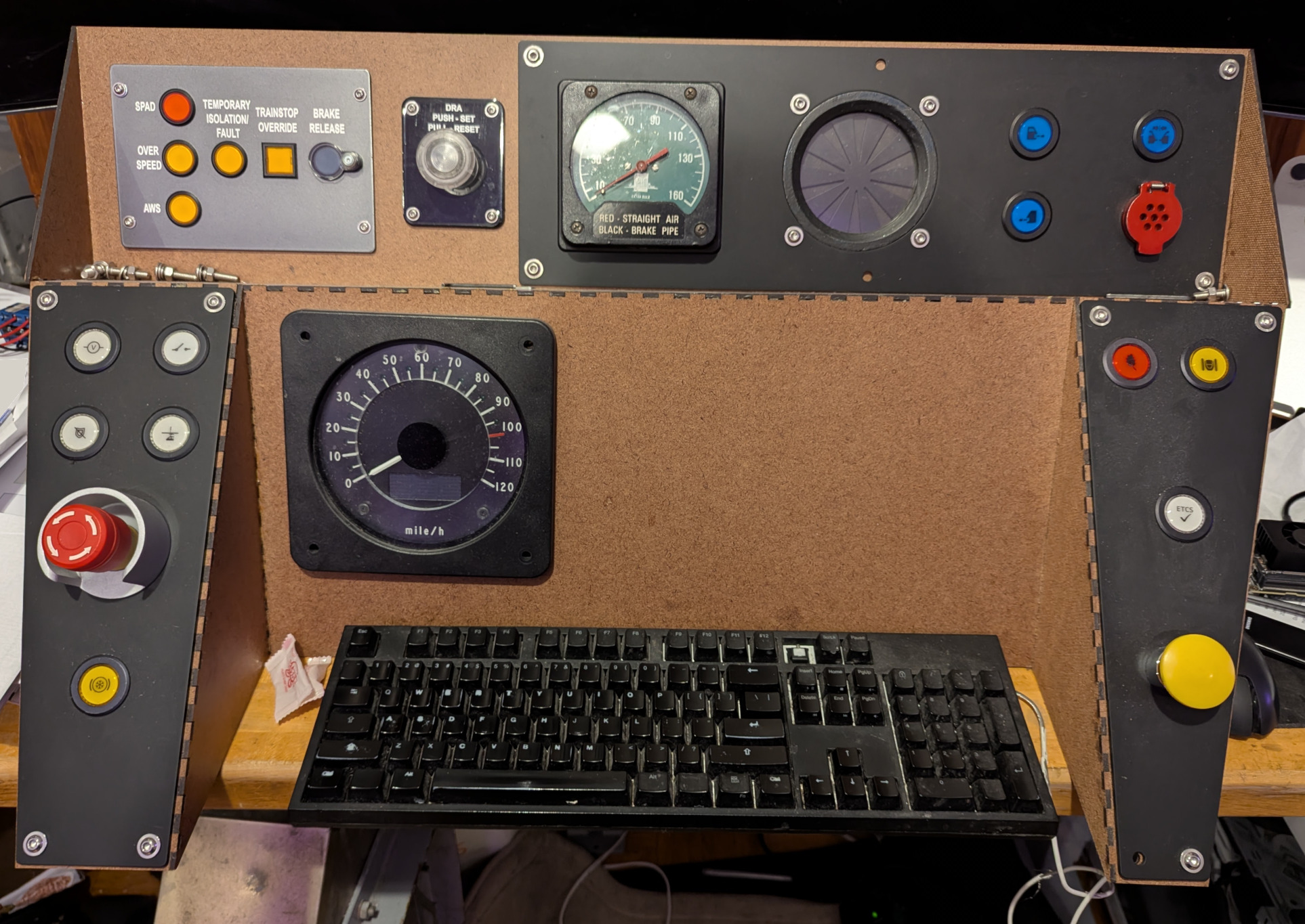
For over three years, I have been building a physical train simulator in my apartment, modeled on the UK Class 80x (Class 800/801/802/805/810) passenger train. I’ve been trying to replicate the instruments and controls in the real cab as closely as possible, in many cases managing to acquire real components, and in others building my own replicas. I’ve gone down rabbit holes of design, from a custom CAN bus transceiver board and a variety of daughterboards to tie the simulator together, to the actual panels on which all of the constrols and instruments are mounted. I usually wait until I complete a component or step before I write a blog post, but over the last half-year, I’ve instead made forward progress on several different aspects of the project. Therefore, this blog post is a status update on these many aspects, each of which will hopefully earn its own dedicated blog post when it is completed.
Headlights
One of the more complex panels on the Class 800 dashboard that doesn’t use an existing instrument or control is the headlight control panel. The real trains have a six-position knob that controls what the head lights (and tail lights) display, a push-on, push-off button to set flashing hazard lights, and a set of LEDs on a diagram of the front of the train that show how the headlights are currently configured. I decided to make my own PCB holding white and red surface-mount LEDs that also acts as a daughterboard for one of the CAN bus transceivers, and breaks out terminals for connecting the selector switch and hazard button. For the PCB, I tested out three options each for the white and the red LEDs, trying to find versions that would have visually similar brightness (and not be too bright). I went through two iterations of the PCB before I landed on the right size, layout, and dimensions, and I also used my current PCB manufacturer of choice, JLC, to make frosted white diffusers for the LEDs connected into one spidery web. Unexpectedly, the hardest part was finding the right selector switch: I knew the manufacturer and even the part number for what I need, but the only way to get it new is to spend hundreds of dollars buying multiples. Therefore, after a few incorrect guesses at eBay listings, I collected all the right parts to cobble together my own six-position selector switch that I believe is exactly what the prototype uses. Of course, I also tested it out with Train Simulator and Train Sim World, although still slightly stymied by Train Sim World not exposing the current output state of LEDs and indicators on trains’ dashboards.
In the eventual dedicated blog post about this panel, I’ll show the PCB iterations, the diffuser, and how the final version works with Train Simulator.
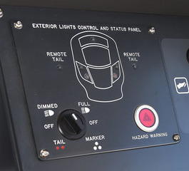 Headlight control panel on a Class 800 EMU
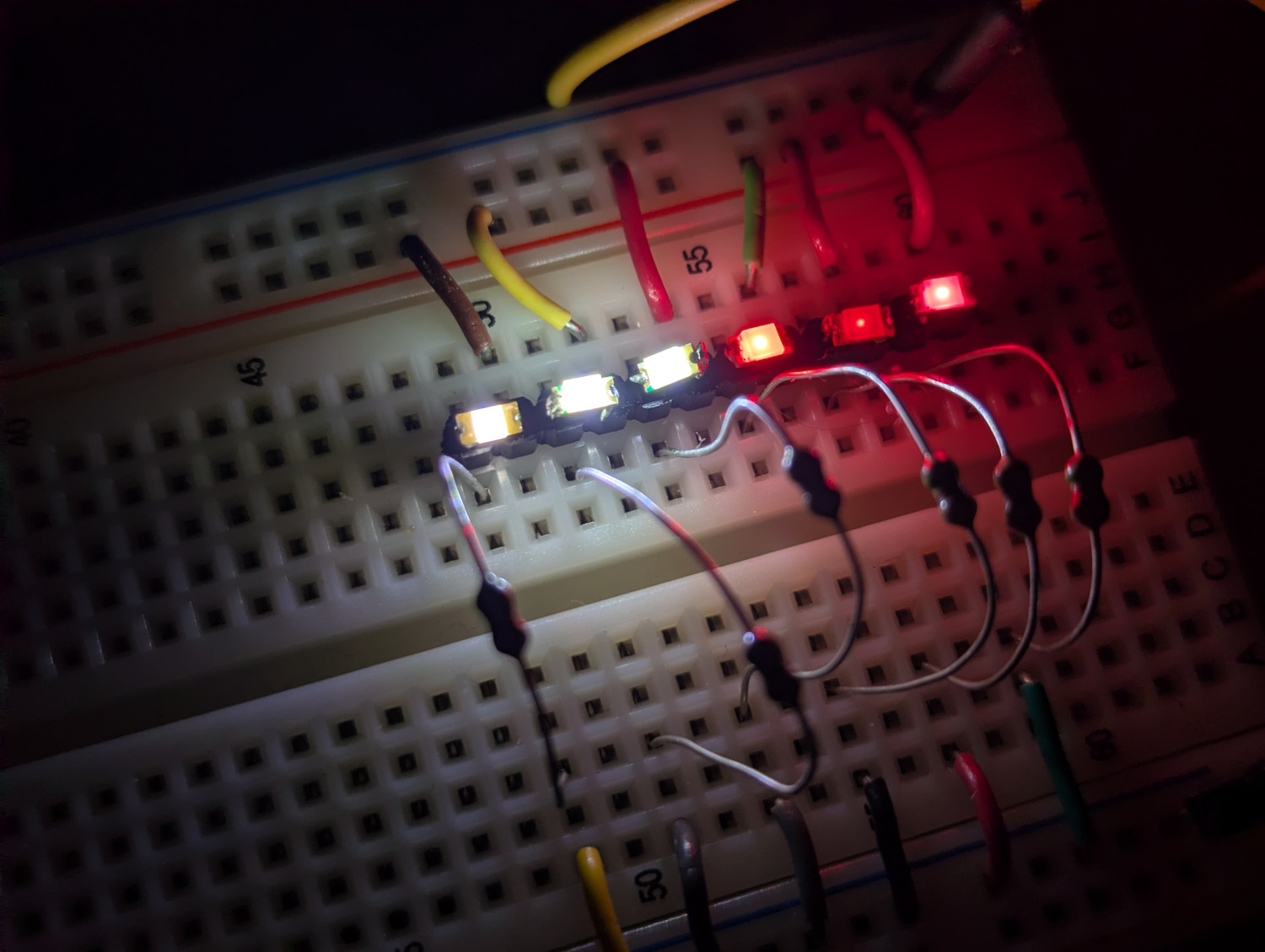 Selecting the best LEDs to use for the headlight position preview
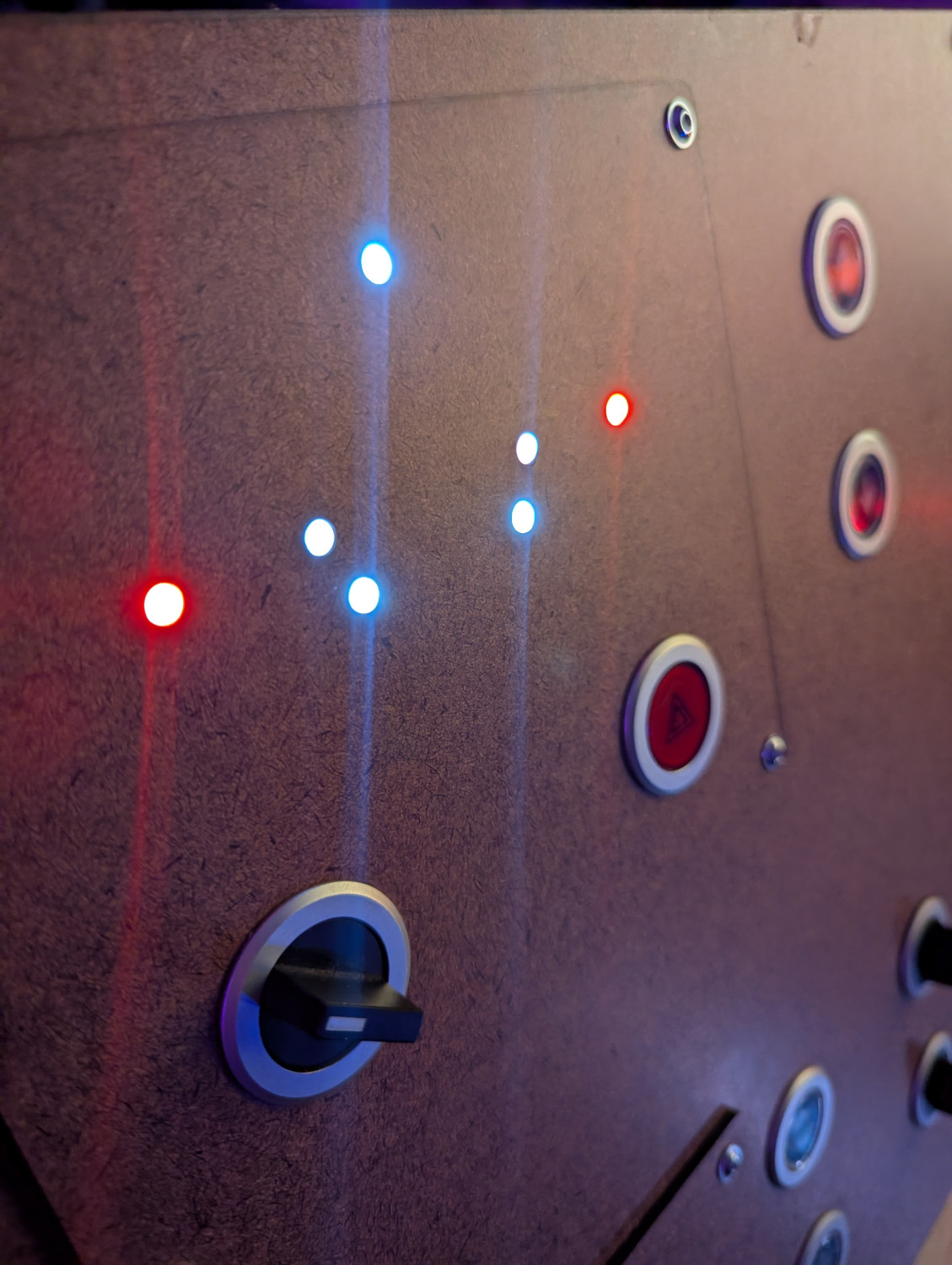 Performing an integration test of the (bright) LEDs in a hardboard version of their panel
Sheet Metal Panels and Labels
Last November, I posted about a hardboard prototype of the center panel of my train simulator, then at the end of December, the full four-section setup that replicates the driver’s controls in a Class 80x EMU. The hardboard version, especially when mounted on the custom table I built, has validated the dashboard concept, but is too fragile to be used long-term. In addition, it doesn’t look realistic: in fact, some commenters thought that it was cardboard. Therefore, my next step was to replace the panels themselves with sheet metal.
As a test, I started with the TPWS panel and the Driver’s Reminder Appliance (DRA). Both are laser-cut and powder-coated steel. With the tireless help of my good friend and expert prototyper Tim “geekboy1011” Keller, we laser-engraved the panels, painted them, and the result is both very professional and prototypical, and with a little bit of clearcoating, hopefully durable as well. The result was far better than I expected.
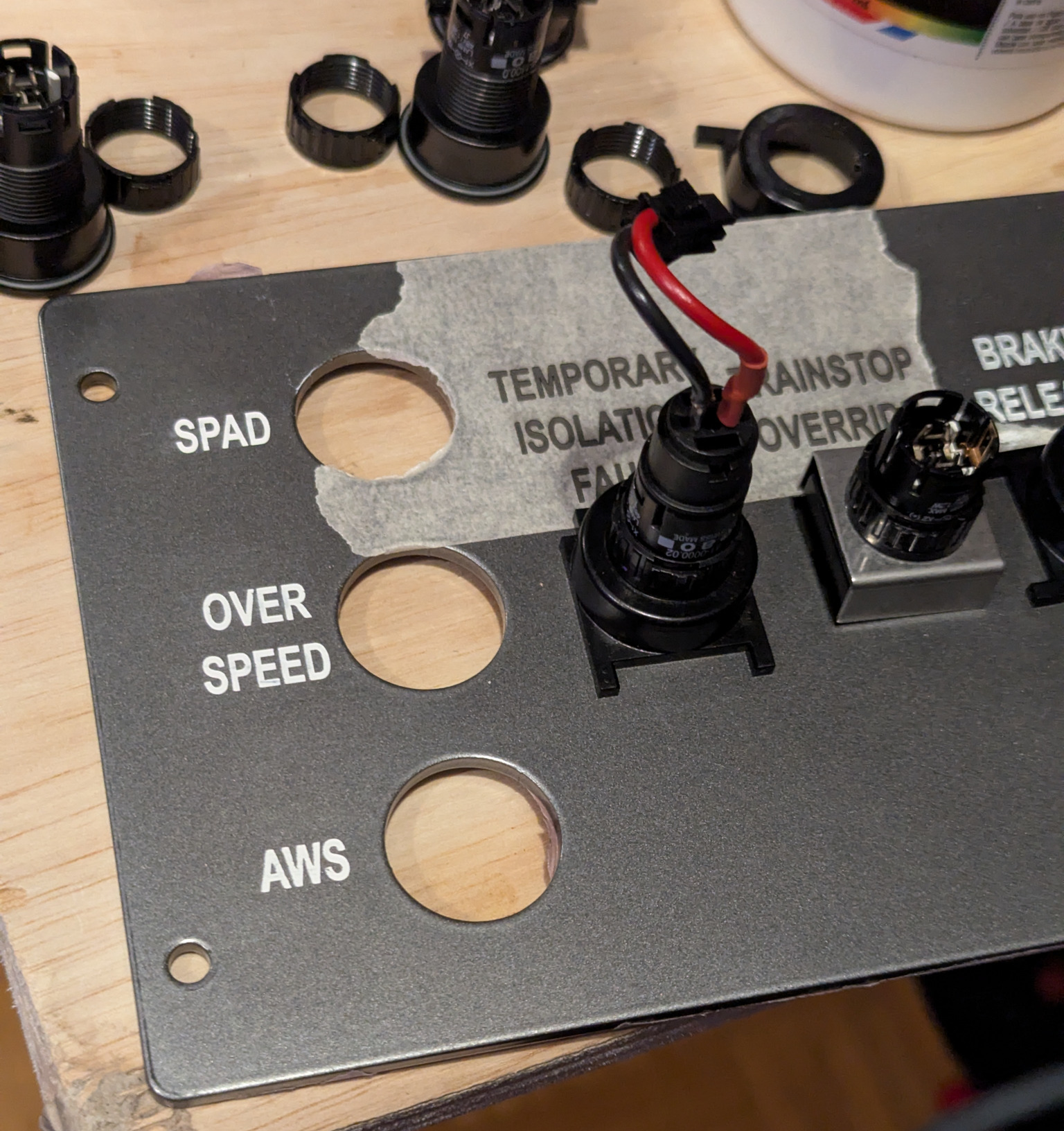 Painting labels on the TPWS control panel
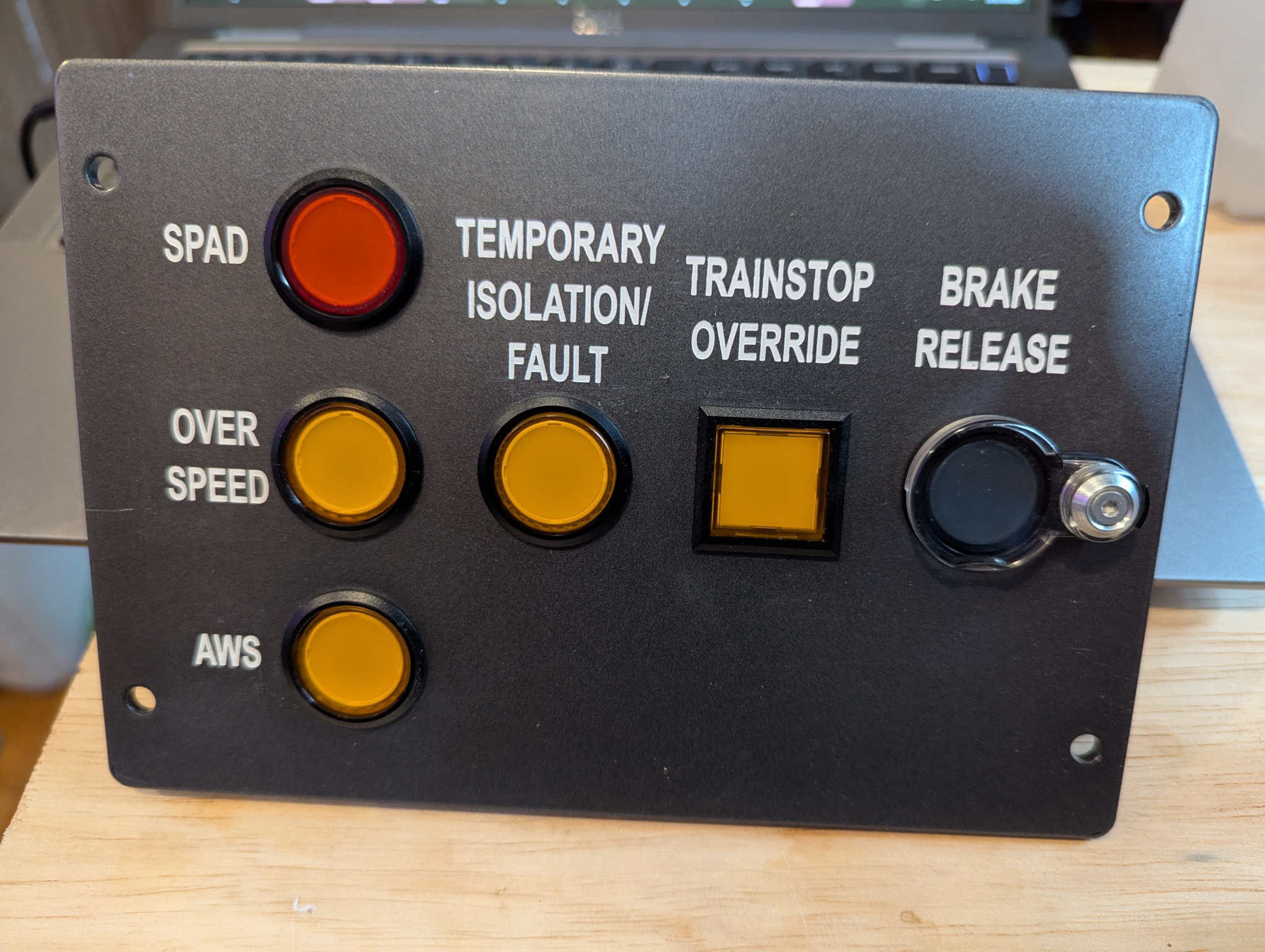 Completed TPWS control panel with all labels
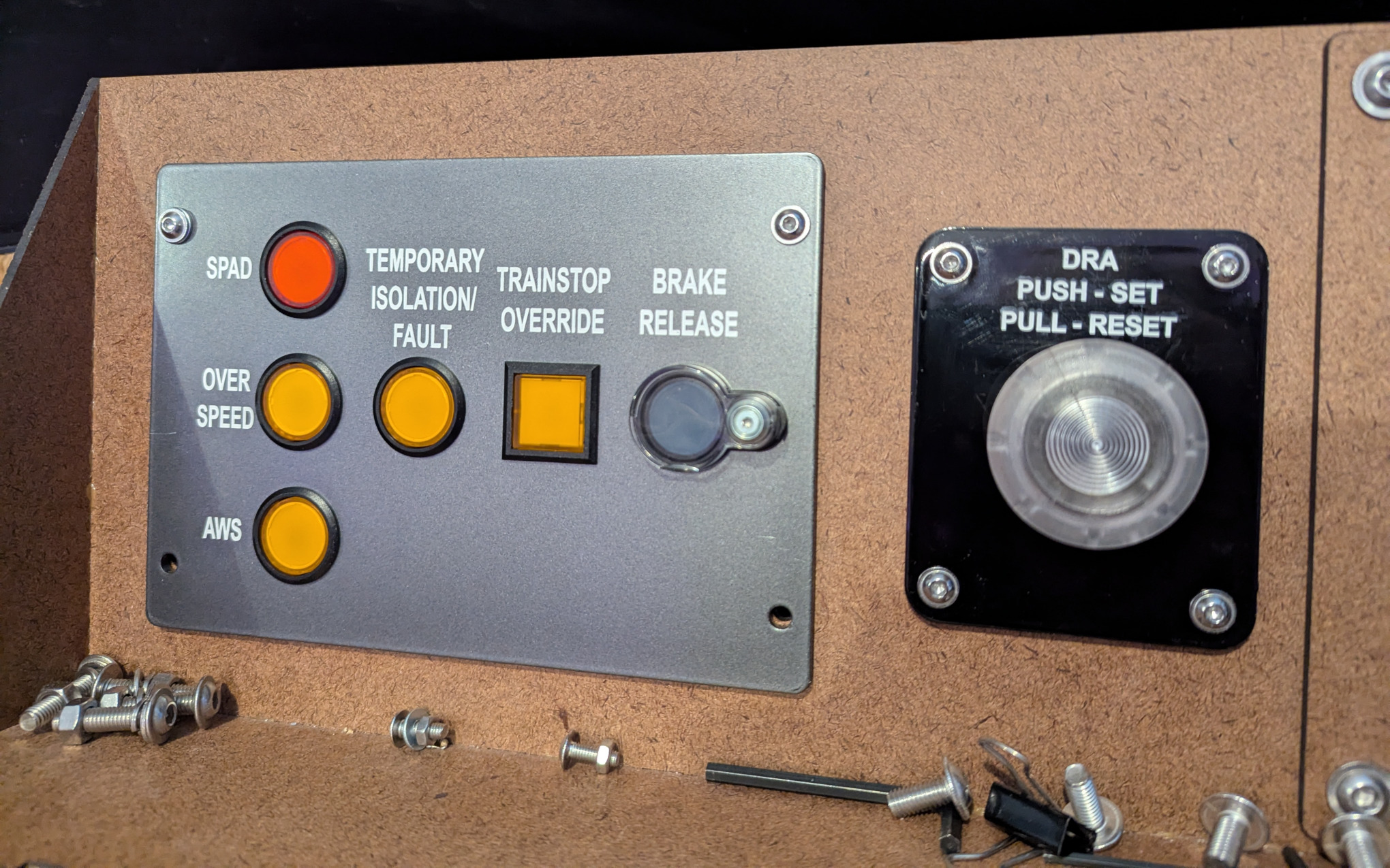 TPWS and DRA panels installed in the Class 800 simulator center dashboard
With this test having proved that powder-coated steel was a workable solution, I set out to get sheet metal versions of all of the other panels. Unlike the TPWS and DRA panels, which were powder-coasted in semi-gloss and glossy materials respectively to match the prototype, these panels were all powder-coated with a matte black material. I received these panels in late March, and spent a while using, testing, and developing my simulator with the blank panels in place. The buttons and switches transferred without incident from the hardboard versions, and the steel versions work well, inlcuding flexing less than the hardboard prototypes. I did discover that they are very heavy for the hardboard and MDF-based supports I had been using, a reason to switch to sturdier plywood backing as soon as I’m able.
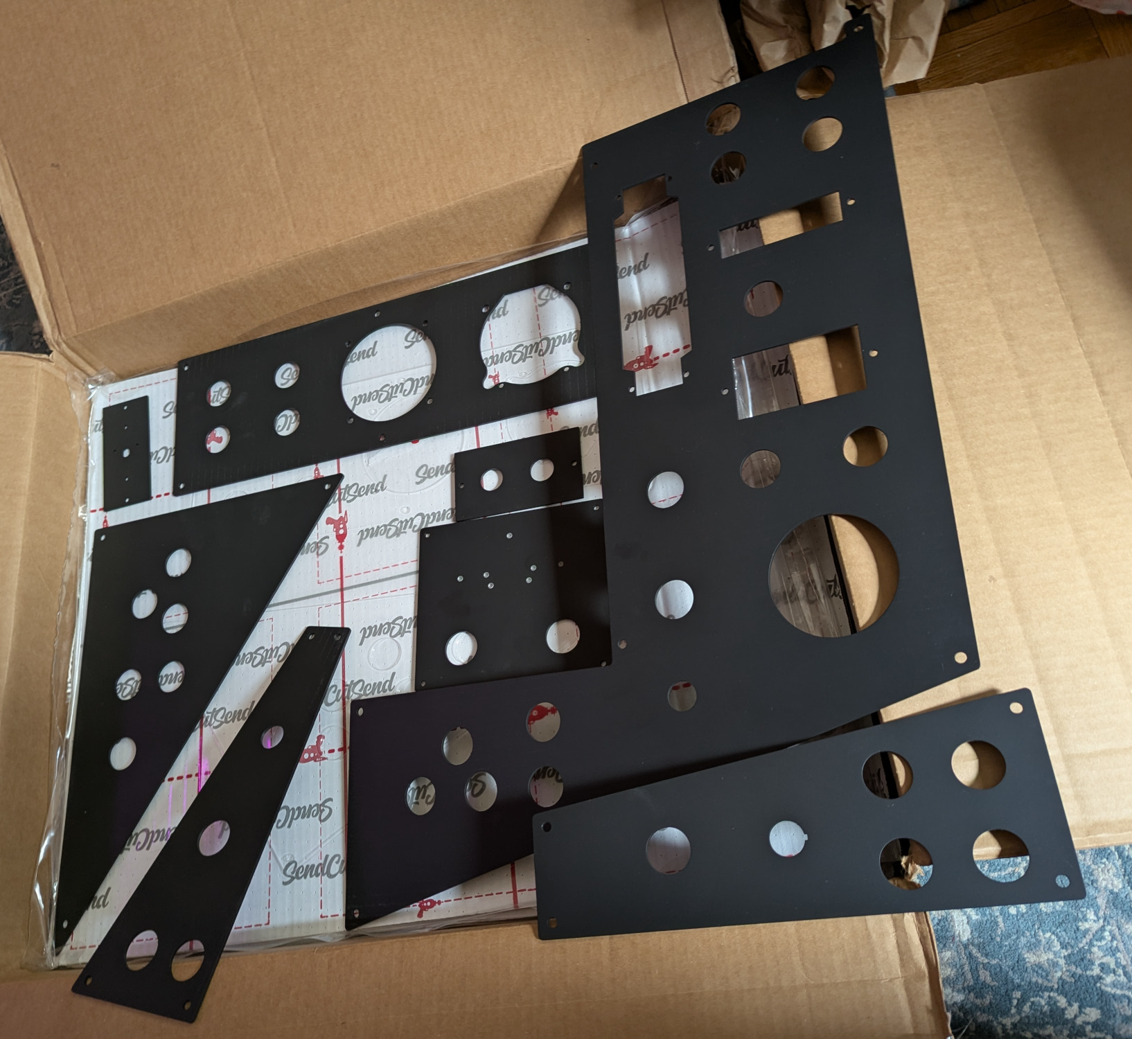 Sheet metal replacements for hardboard panels
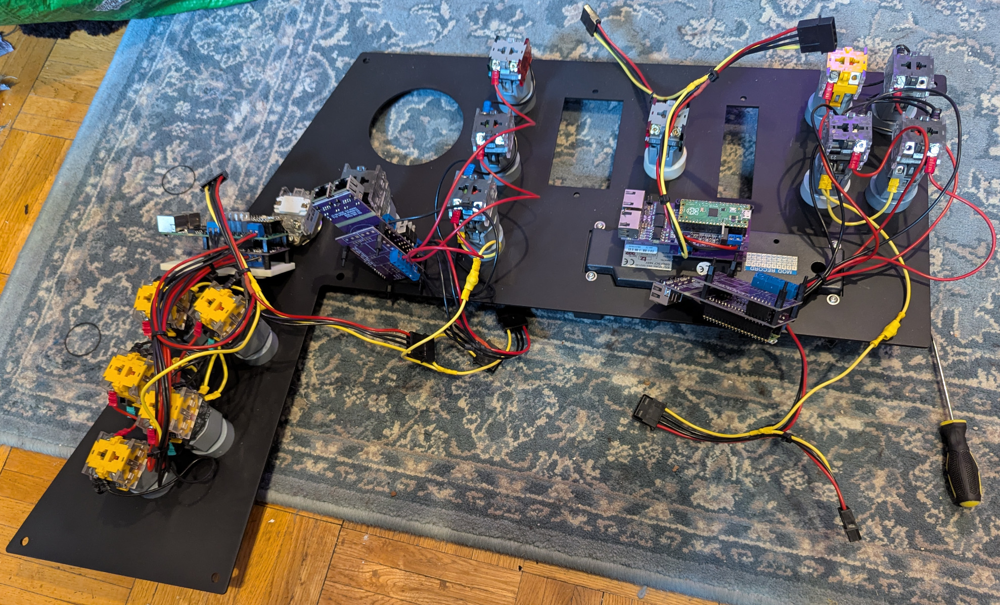 Installing components in the right-hand panel
Class 800 center panel, partially using sheet metal panels
Installing components in the right-hand panel
Class 800 center panel, partially using sheet metal panels
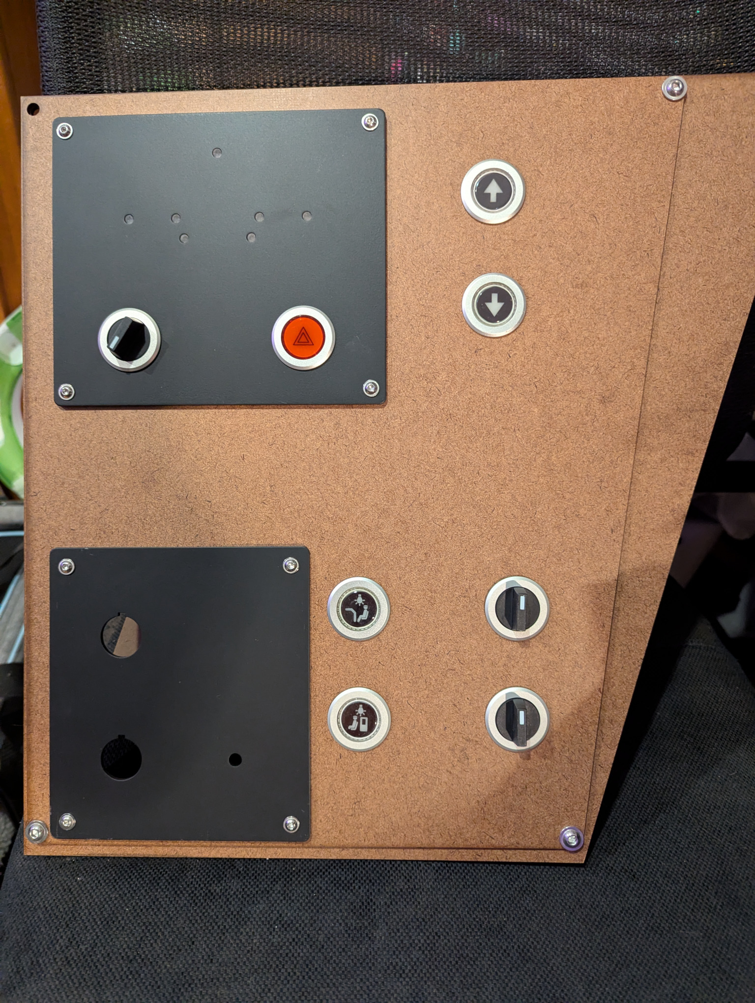 Testing headlight and environmental controls with sheet metal panels
I thought that labeling these panels would be as easy as the TPWS and DRA panels had been. Alas, even beyond slight challenges with geekboy1011’s laser engraver, I discovered that instead of wiping off cleanly, white acrylic paint seeps into matte powder coating. I will need to change my approach to fabricating these panels, ideally without wasting the money I’ve already spent on these panels. I’ll share my latest progress in a future blog post about the panels.
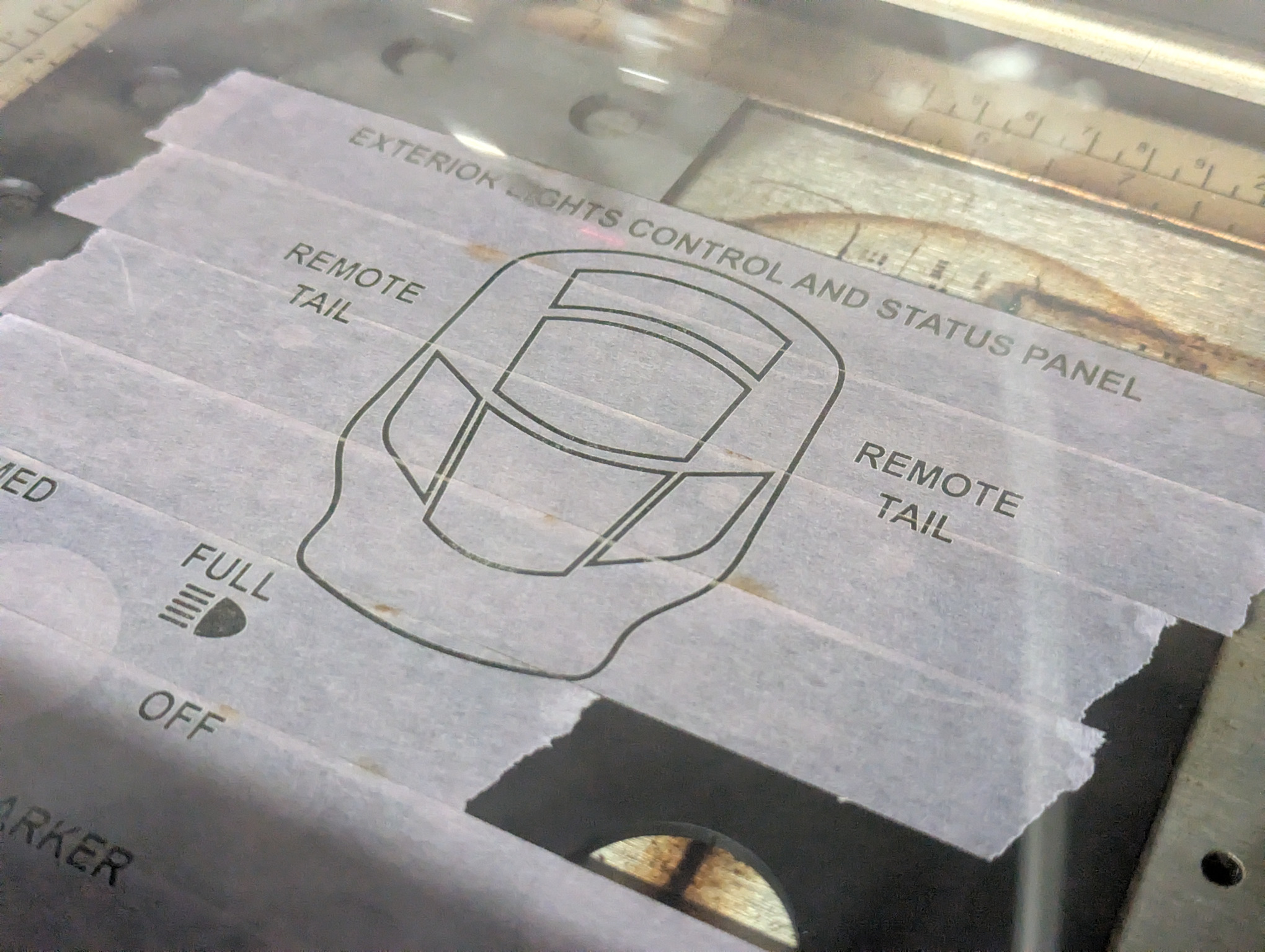 Laser-cutting the Class 800 diagram on the headlight control panel
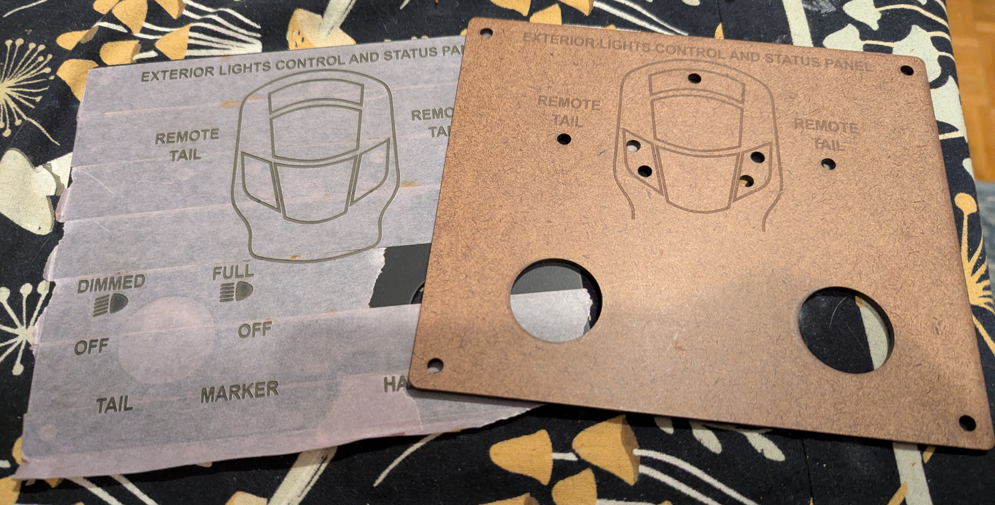 Hardboard and metal versions of the headlight control panel
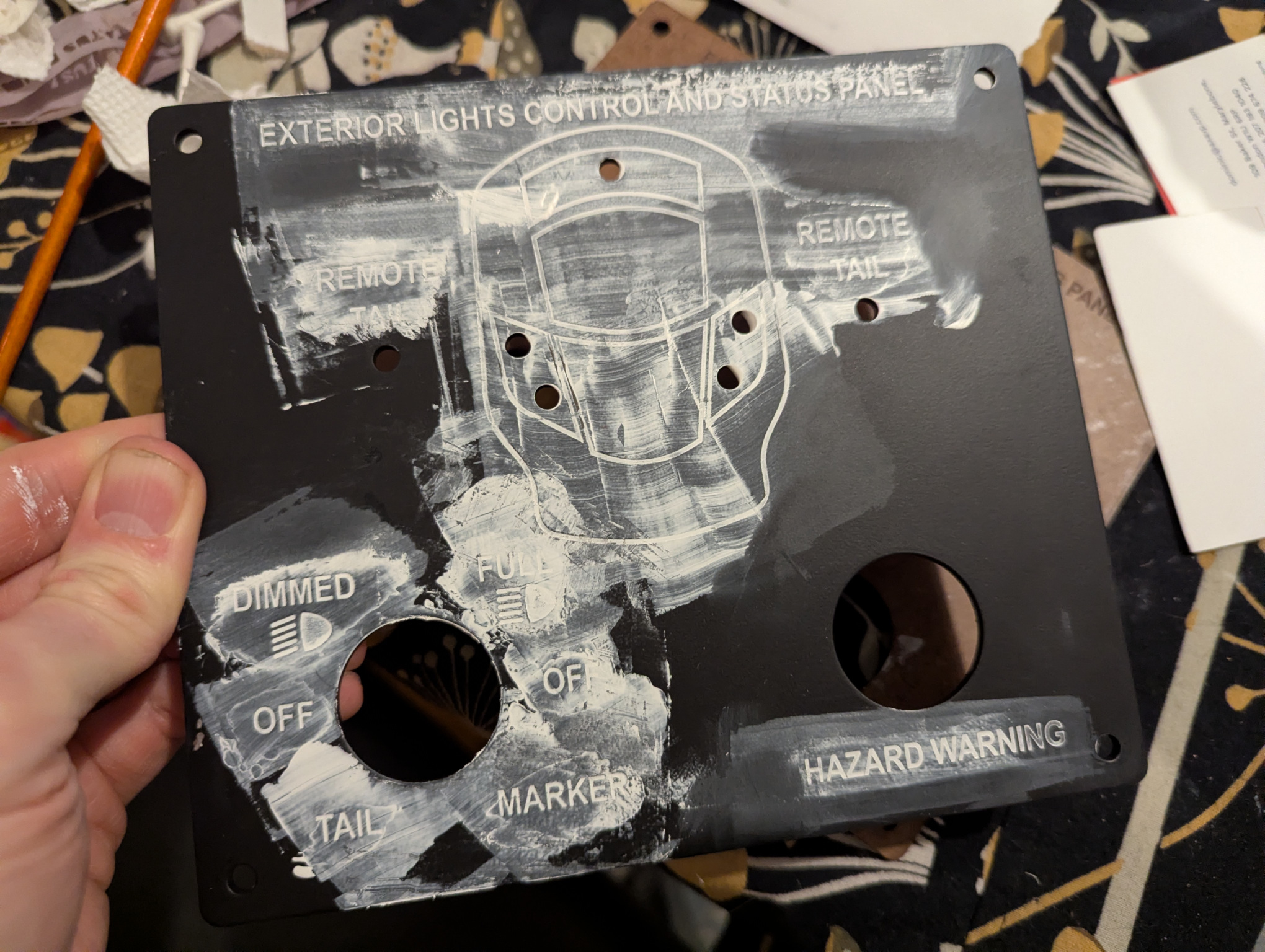 Suboptimal tests for inking/painting the matte panels
Testing More AWS Sunflower Varieties
One of the earliest real instruments I interfaced with Train Simulator was an AWS “sunflower”, the evocatively nicknamed black-and-yellow instrument that allows a UK train driver to see if the last signal they passed was at an aspect other than clear (green) (or if they’re approaching a significant speed reduction: basically, if they should be proceeding cautiously). In that post, I opined that “I anticipate that I will let Train Simulator provide the warning horn/buzzer and “clear” bell itself rather than providing those as physical components.” However, more recently, a kind colleague in this space connected me with three smaller AWS modules embedded in units that also produce the real warning horn and clear bell: one with a mechanical sunflower, and two with illuminated LED sunflowers.
As much as I love the big mechanical sunflower and prefer not to deafen everyone around me, I had to see if I could interface these more realistic AWS sunflowers with my setup. To that end, I started with the unit with the miniature mechanical AWS sunflower, disassembling it to document its electrical connections. As shown in the video below, I validated that I could make the sunflower sound both the horn and bell sounds, but this unfortunately requires high-side (common cathode) switching, while the FETs in my CAN bus transciever board all provide low-side (common anode) switching. I went on a side quest to cram even more into my I/O daughterboard, allowing four of its five FETs to be configured for either low-side or high-side switching.
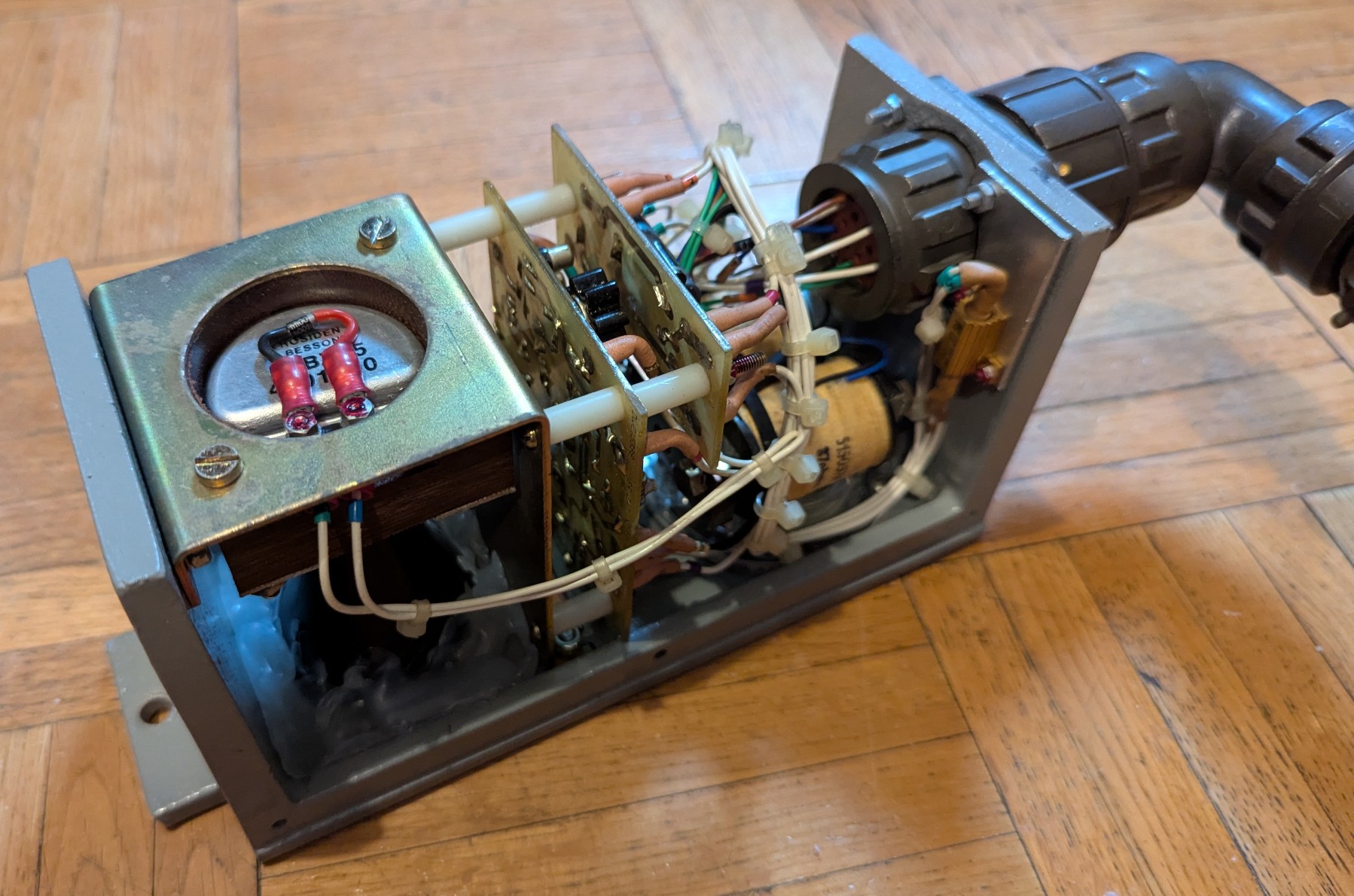 Inside a miniature mechanical AWS sunflower that can also generate sound
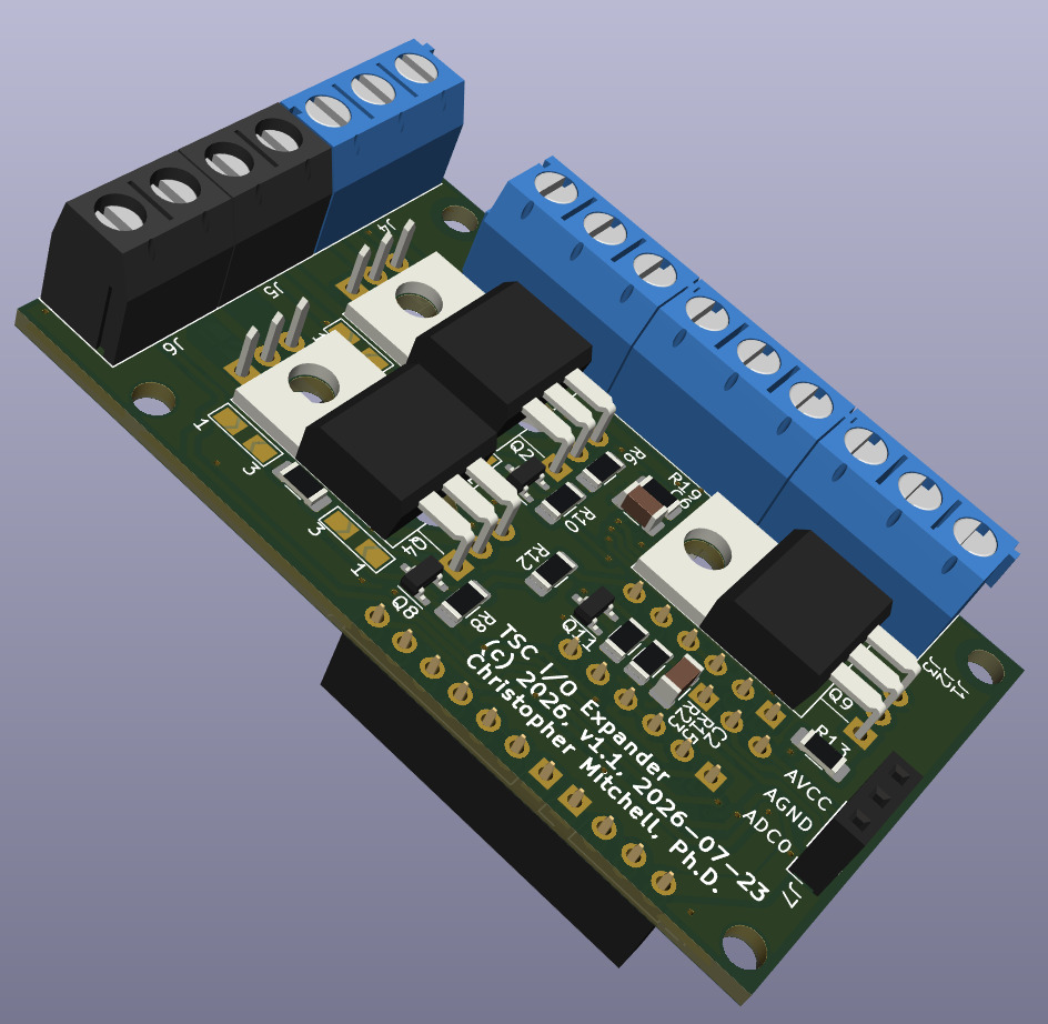 Designing a modified I/O daughterboard for my CAN bus transceiver that handles high-side switching
When those circuit boards arrive, or possible even sooner, I’ll show off the result, and I’m seriously considering embedded the more prototypical miniature LED sunflower in my dashboard, even though I’ll be lacking the satisfying mechanical thunk of the electromagnetic ones.
Miniature mechanical AWS sunflower with clear bell and alarm horn, testing sound only