
RailScan: First Point Clouds from Railroad Museum Scanner
In my last post, I introduced my project to build RailScan, a hobby scanner for railroad museum infrastructure. I described the goals of this project: to scan a railroad museum, get a complete 3D point cloud of the track and infrastructure, and perhaps also be able to automatically extract the locations of the rails and overhead wire. I broadly validated that my chosen compute platform, a Raspberry Pi 5, could communicate with a low-cost LiDAR scanner (an STL-27L) and a ublox ZED-F9R-based GNSS board. I also decided that I would mount the sensor package, compute, and a battery in a small package mounted onto a tow pocket on one of the museum’s trolleys (or trams, for our UK- and Europe-based friends). I designed a hardware platform that could be laser cut out of plywood, and send off my design to be fabricated.
I received all the pieces right before July 4th, and assembled my hardware module; a bit over a week ago, I performed the first tests with the LiDAR scanner assembly mounted on a trolley (tram, for our British friends). The setup looks like this:
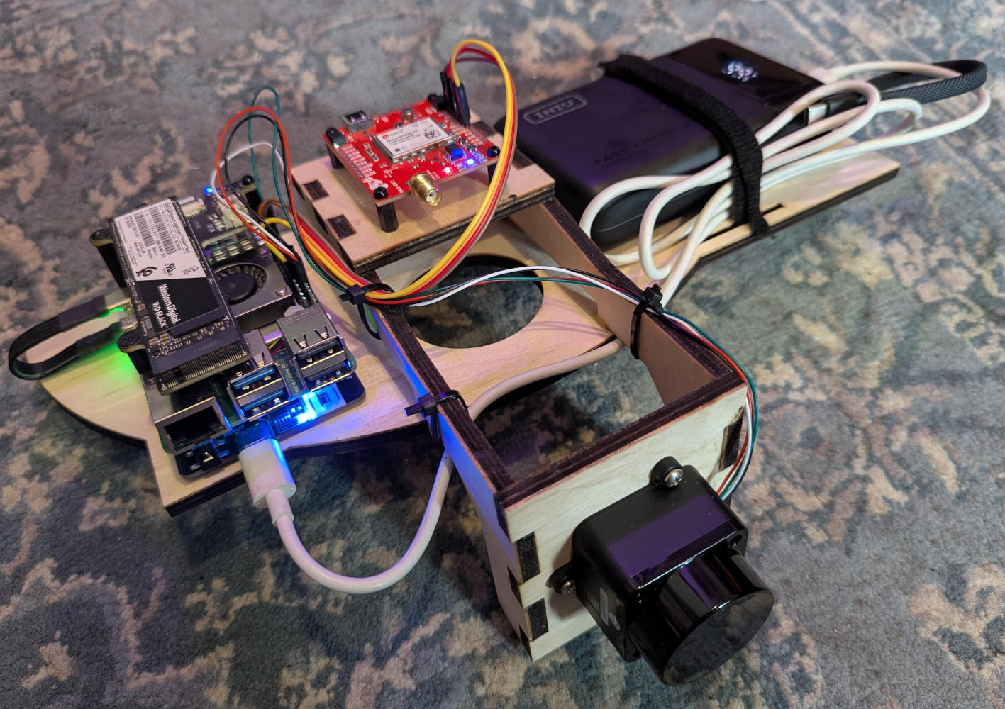 Sensor platform
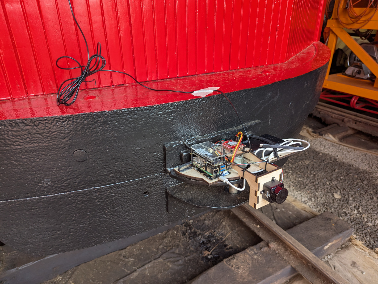 Mounted on trolley tow pocket
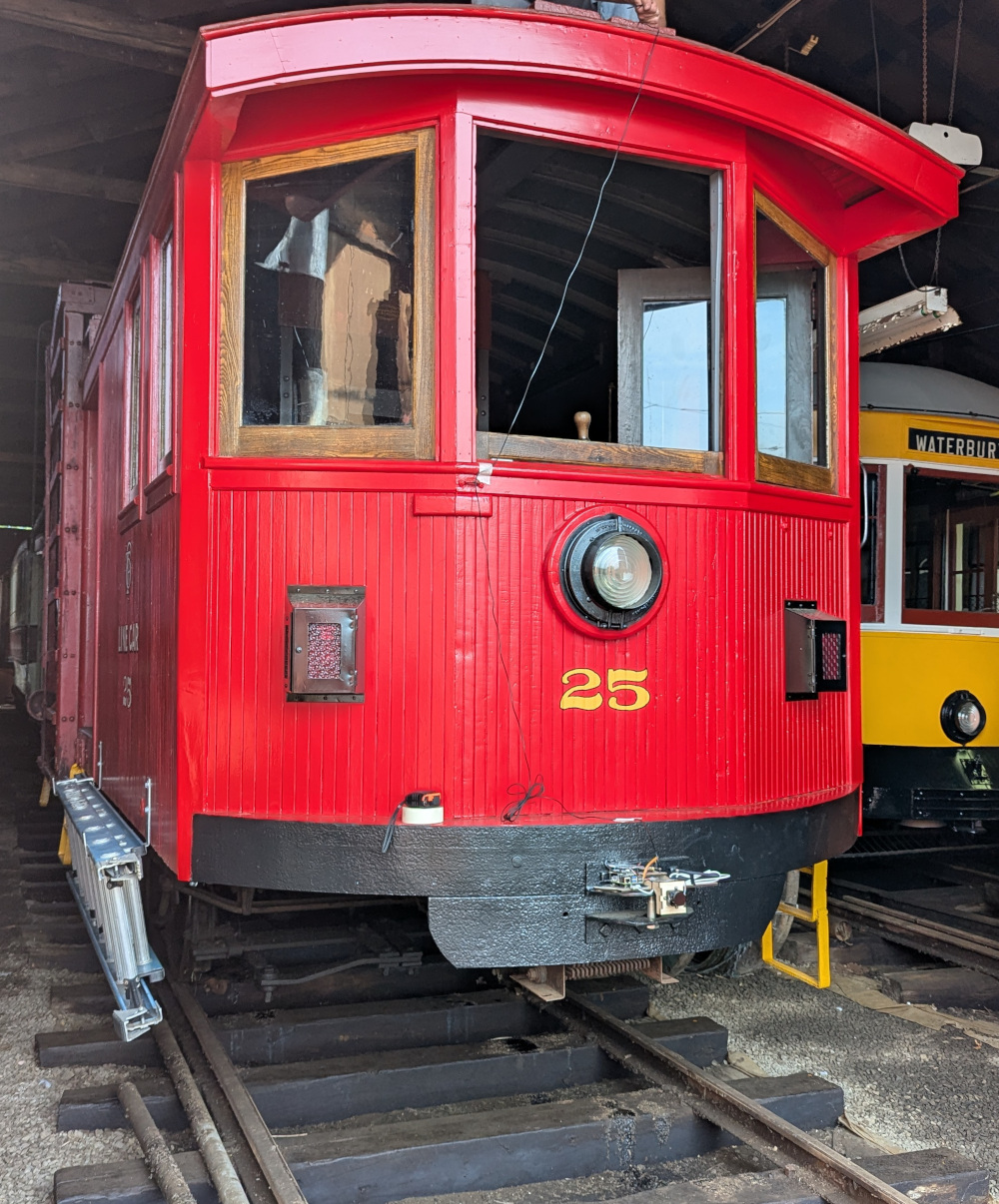 Antique line car, ready for modern scanning
In addition to the plywood mount with LiDAR scanner, Raspberry Pi, battery, and GNSS module on the tow pocket, there’s also a GNSS antenna mounted on the top of the trolley (in a nondestructive way - zip ties!). Because it’s not possible to perfectly level the LiDAR scanner and IMU-containing GNSS module, nor is it possible to ensure they’re facing perfectly forward, a part of setting up the system is running two calibration passes. The first measures gravity with the trolley perfectly still to determine any pitch or roll, and the second computes forward (and backwards) acceleration vectors while accelerating or decelerating along a straight track to determine yaw. Unfortunately, I found a bug in the yaw calibration, and didn’t have the time to fix it.
A few days ago, after making some changes and fixes to the software, I tried again, successfully performing calibration, and then running the trolley along a U-shaped portion of track that also includes a number of switching tracks, then into a barn. I discovered one obvious bug, that the system flips the perceived angle of the LiDAR-scanned points when the trolley moves backwards, so that points that should be on the left show up on the right, and vice versa: this yields a “ghosting” effect when reversing the vehicle, as points from the same object appear on both sides of the track. I notice some wiggling that I’m not sure the source of: GNSS/IMU imprecision, dead reckoning imprecision, poor vibration damping, or all of the above. I also unfortunately note that the module largely failed to detect the overhead wire, one of the main goals of this project, so I will need to explore if it is possible to mount the assembly higher on one of the trolleys.
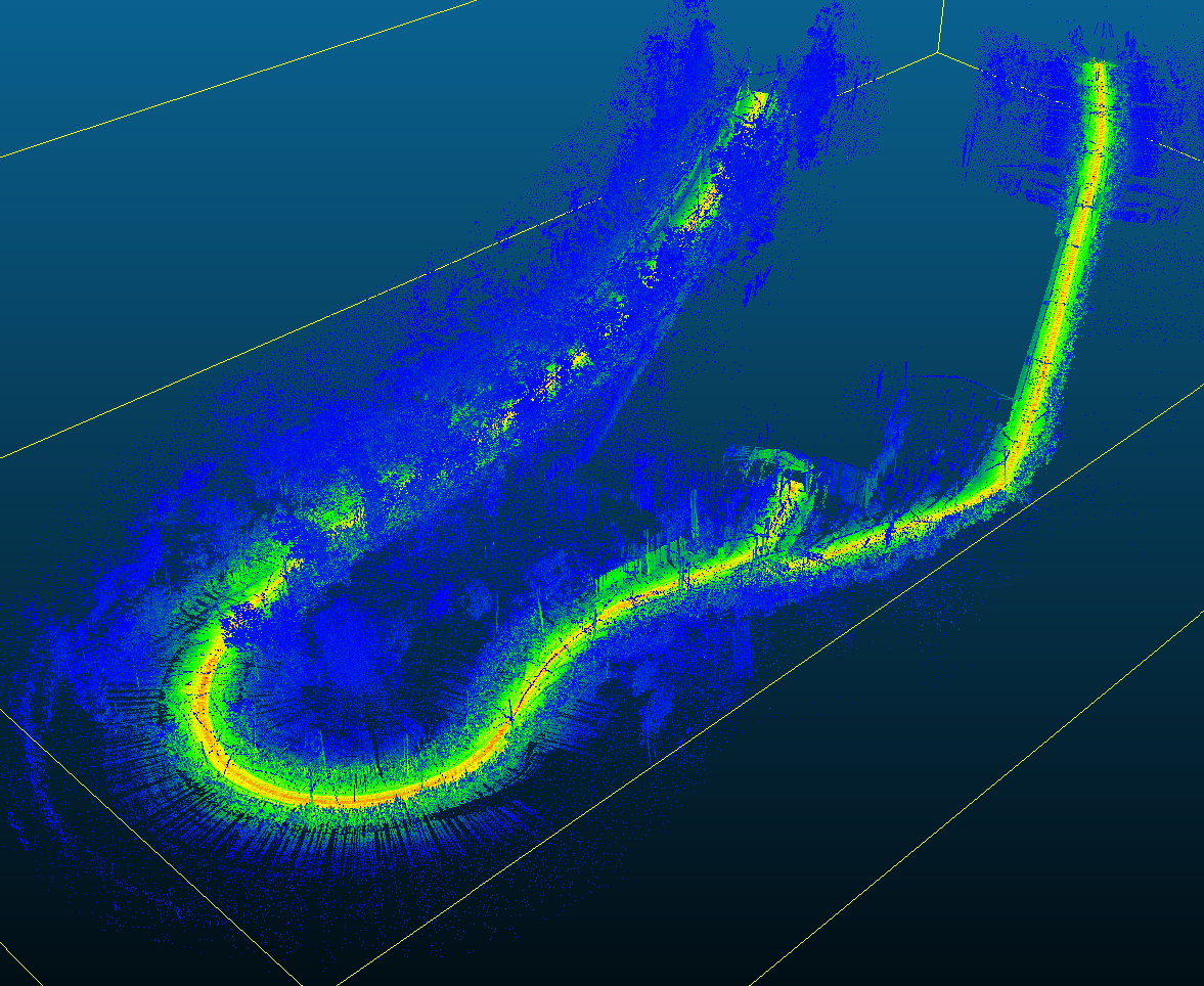 Entire track section scanned, overshadowed by trees and infrastructure
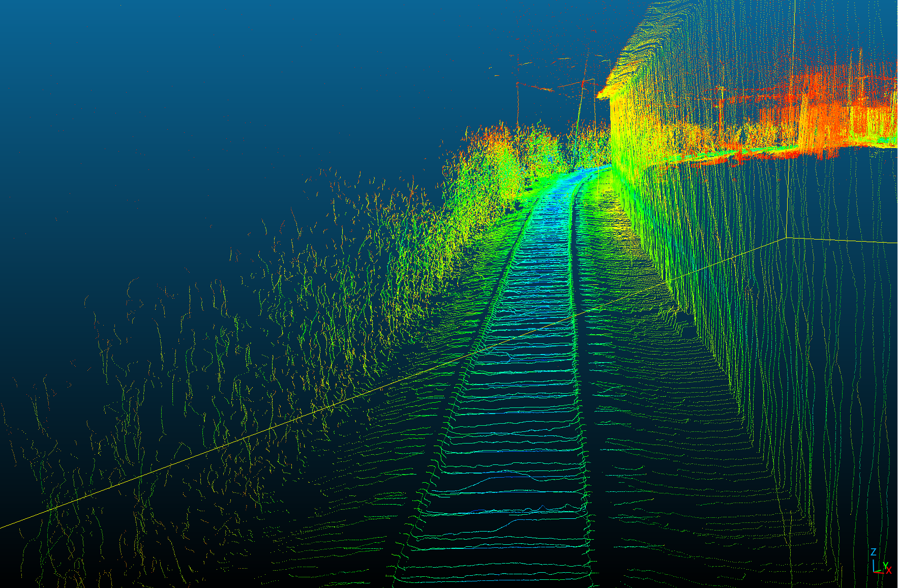 Section of track with plants on the left and a storage barn on the right
I intend to fix the reversal problem and test again on my next visit to the museum, but in the meantime, please enjoy some eye candy! Colors indicate the intensity of the LiDAR returns, including the surprising result that the intensity of the returns differ enough between ballast (roadbed, or gravel) and wooden ties that it may be possible to actually detect the individual ties. Guardrails also show up clearly in the scans, and line poles and span wires also often are visible.
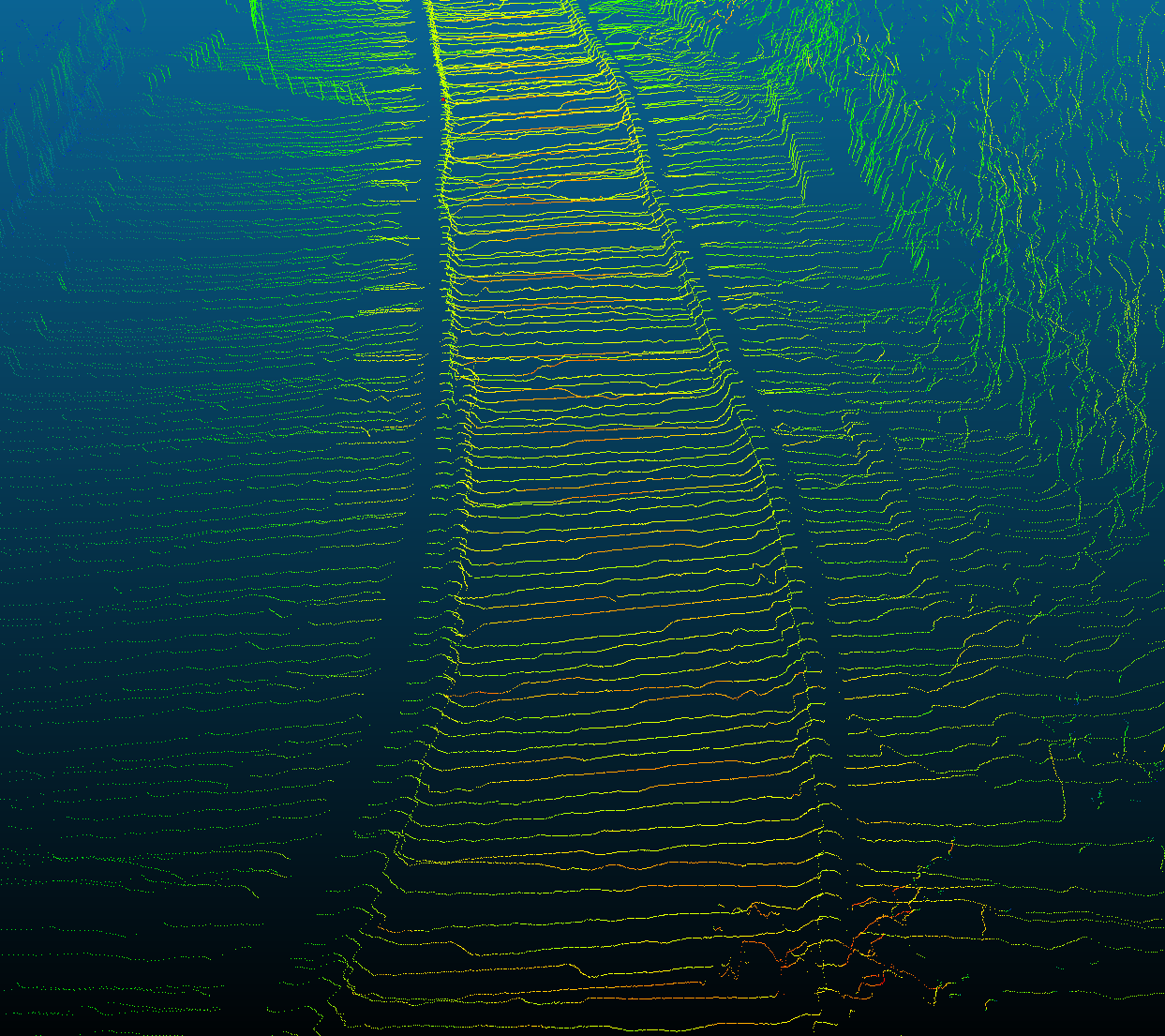 Individual ties visible
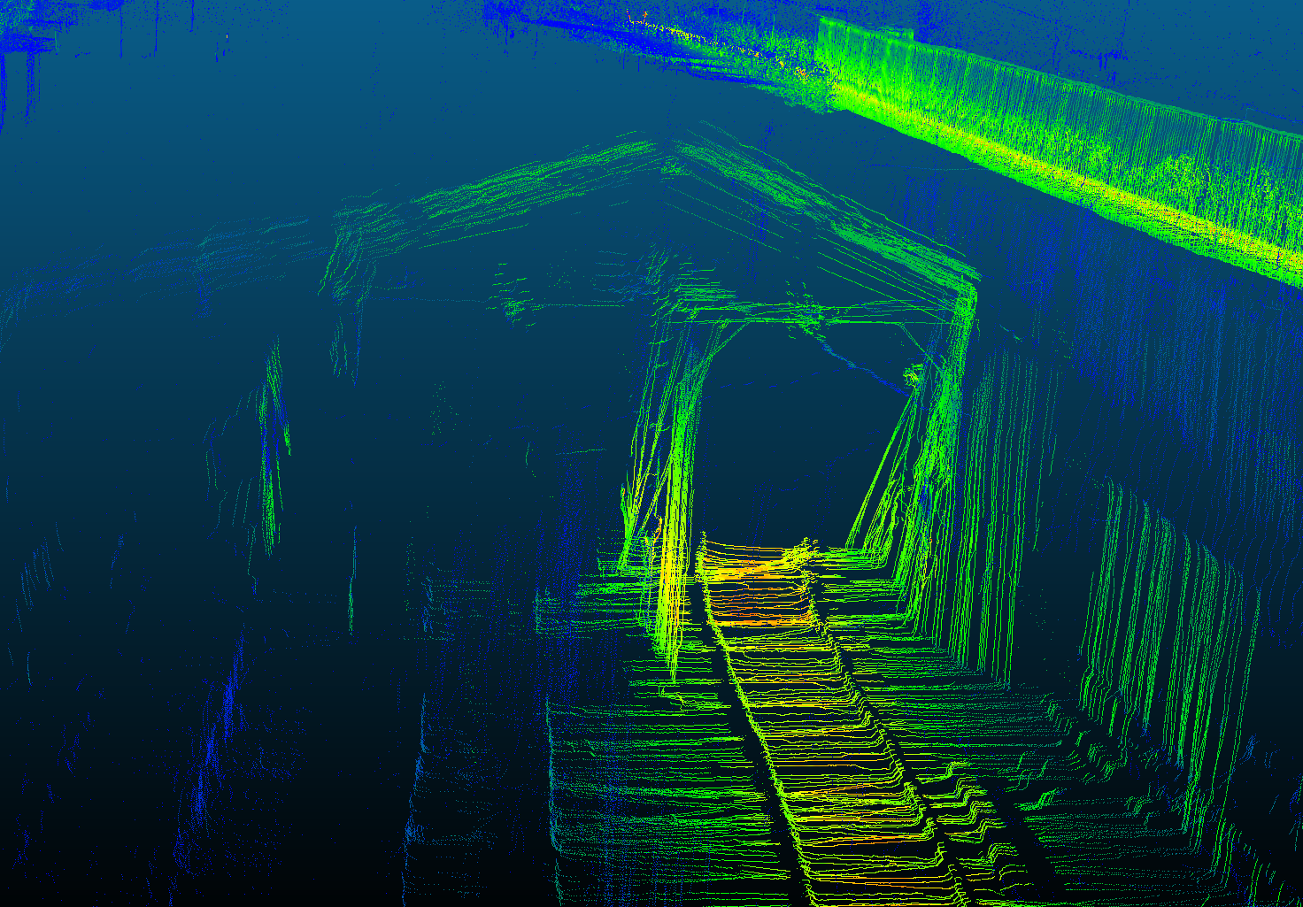 Guardrail on a curve