
RailScan: Railroad Museum Track and Wire Scanner
For nearly ten years, I have been volunteering at a nearby train and trolley museum. I got started helping out by putting some of my electrical engineering background to work, assisting with electromechanical restoration of control systems in old subway and trolley cars preserved in the museum’s collection. As I spent more time at the museum, I became qualified as an operator (or motorman or driver, as different places call the position), I started helping out with maintaining and fixing the overhead line that feeds DC power to our fleet, track repairs, mechanical maintenance and restoration, and various other other priorities at the museum.
Meanwhile, over a very similar period, I founded and grew a geospatial AI startup called Geopipe, including as cofounder and first engineer building a substantial portion of our technology. We created a product to automatically generate rich digital twins of the real world for gaming, simulation, and architecture, by ingesting raw sensor data about the world and processing it through an “AI” (machine learning and computer vision) pipeline to determine what is in the world, not just how it looks. Among the data we ingested were LiDAR, point clouds created by bouncing a spinning laser off the world and recording a point everywhere it bounces off something, as well as rasters (2D data) and vectors that describe what’s in the world. Naturally, therefore, I’ve always been interested in the idea of building my own LiDAR scanner to collect the type of point cloud data we analyzed at Geopipe.
A perfect opportunity arose after quite a few years volunteering at my museum. We have a variety of careful, specific techniques to measure the track and overhead wire and identify when the track is “out of gauge” (slightly wider or narrower than it should be) or the overhead wire is slightly lower or higher than it should be. I was curious if a LiDAR scanner could be deployed to collect an overall map of the museum, and at least a rough guesstimate of the track gauge and wire height everywhere along the tracks. I knew it wouldn’t replace manual inspection, or be a serious tool for safety-critical infrastructure, but it seemed like an interesting exercise. Keeping this in the back of my mind, I began occasionally looking into LiDAR scanners that were inexpensive, for example aimed at hobby robotics use, that would spin fast enough and have a sufficient range and accuracy to be able to see both the railheads and the wire overhead. I also needed the LiDAR scanner to work outside in at least indirect sunlight.
When I found the STL-27L LiDAR scanner, thanks in no small part to Reddit and especially to the PiLIDAR project, it seemed to fit the bill perfectly. It scans in a 360-degree circle (some scanners only scan a portion of the circle), its range stretches from 3cm to 25m, it scans at 10Hz (although the motor control can drive it at between 6Hz and 13Hz), and its ranging accuracy is quoted as averaging (?) 1.5cm at up to a 2m distance. I had some questions about whether the accuracy was good enough for my application, especially for measuring track gauge where a quarter of an inch (6.4mm) can be the difference between in-gauge track and slightly tight gauge, but it seemed like a good place to start. I also knew that I was going to need to localize the LiDAR points I scanned. I suspected that simple GPS (GNSS) wouldn’t be accurate enough, especially inside car barns where the equipment is stored. Research eventually led me to u-blox’s ZED-F9R fused GNSS module, namely the Sparkfun breakout board integrating the unit with an IMU. This module not only does very accurate GNSS positioning, it also performs sensor fusion with an Inertial Measurement Unit (IMU), enabling it to very accurately compute position, heading (pose), velocity, and acceleration, including via dead-reckoning when indoors or otherwise GNSS-challenged. It also specifically has models that enable it to improve its accuracy when mounted on cars, scooters, bikes, and as of version 1.40 of the firmware, rail vehicles. With the GNSS module, I can accurately take the plane of points found by the LiDAR scanner and accurately place and pose it in absolute coordinates in the real world. Put all those scans together, and you get a complete 3D point cloud of the entire track and infrastructure at the museum.
To tie it all together, I am using a Raspberry Pi 5 with an SSD for reliability. I previously had a Li-Poly battery-based power supply for my Raspberry Pi 4, but it doesn’t provide enough current to properly power the Raspberry Pi 5. Therefore, after yet more research, I will be using a 20Ah USB battery pack that can push 45W over USB PD paired with a board that converts that to 5V at 5A for the Raspberry Pi. Here’s the hardware testbed with the GNSS board and the LiDAR scanner I’ve been using to build and test the software.
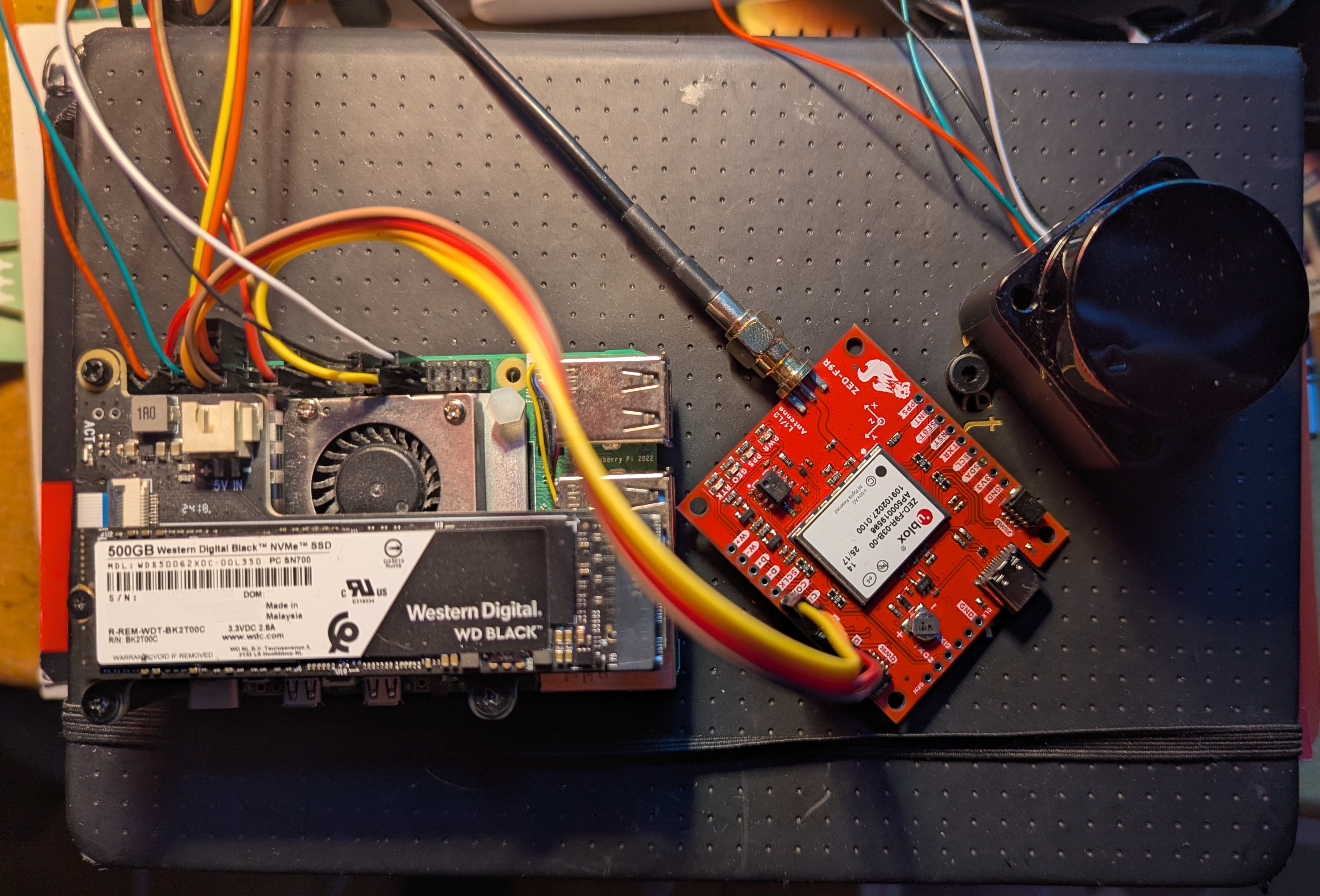 GNSS and LiDAR scanner testbed for museum scanning
Long before I began building software to integrate the GNSS module and the LiDAR points into a cohesive whole, I started by simply communicating with the LiDAR sensor. I used the documentation to write a self-contained C++ library to communicate with the LiDAR scanner. As a test, I used it in a simple program that would collect points over a short period of time, then combine that with a user-supplied, guessed constant speed (e.g., 5mph) to use the timestamps attached to the points to stretch the individual 2D scans, consisting of (y, z, time) points, into 3D (x, y, z) points. Here’s an example of such a (rough) scan, including a great result of the same slice of the interior of the vehicle over and over again, with a not-so-complete view of the outside world, possibly at least partially challenged by reflection or refraction through the window.
 Sample LiDAR point cloud collected by scanning without a GNSS module or IMU, and simply guessing the x-coordinate of each point along the direction of travel based on multiplying the time by the human-estimated speed.
Next, I have been writing the software to combine the fused GNSS+IMU positions and LiDAR scans into a correct point cloud of the museum. Among other details, this requires:
- Correctly calibrating the GNSS+IMU to know precisely how it is oriented, including whether it is tilted slightly along any axis.
- Storing both point cloud files that can be read by other programs as well as information about the trajectory of the LiDAR scanner.
- Differentiating different runs, including along the same track, that might not be perfectly registered with each other due to GNSS+IMU imprecision.
- Locating rails and the overhead wire in the point clouds.
- Correctly handling guard rails, switching tracks, and wire frogs, among other interesting real-world details and occluders.
I have also been working on putting the hardware intro a form appropriate to actually try using to scan real tracks at the museum to test it out. Instead of couplers, trolley cars often have “tow pockets”, into which a metal bar can be slotted using which a locomotive can pull the trolley. One candidate trolley for testing this project has a perfect tow pocket extending out from the body of the car, so that a LiDAR scanner mounted on the end of the pocket will see only the right of way, and none of the structure of the trolley itself. I’ve designed a platform that mounts on the tow pocket that will hold the Raspberry Pi, GNSS board, LiDAR scanner, and a battery for the Pi, and bolts to the tow pocket through the hole for the tow pin. My trusty parts source SendCutSend is fabricating the platform out of plywood, after which I’ll assemble the result and test it out.
Next time, I’ll share test results and lessons learned from version 1.
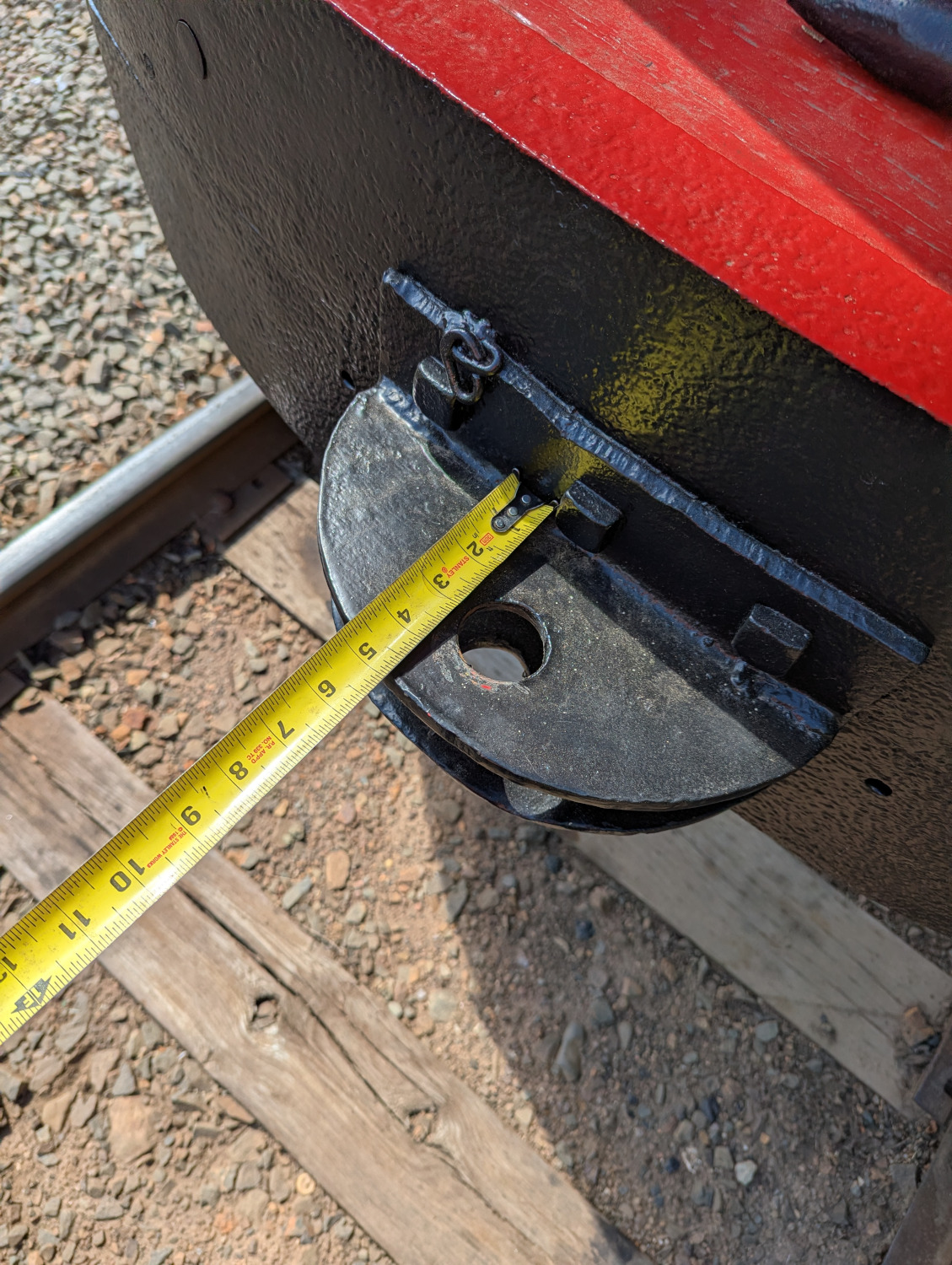 Trolley tow pocket
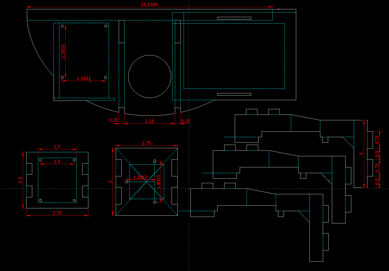 Components of platform to mount scanner
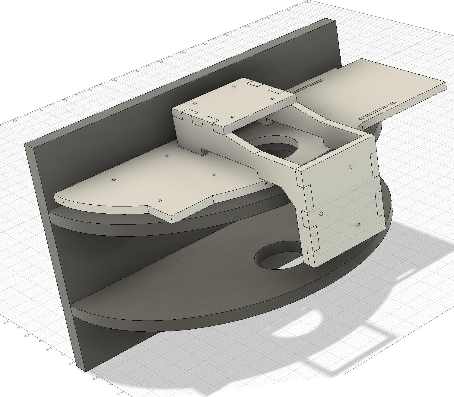 Platform to mount scanner on tow pocket