Train Simulator Controller: CAN-Connected Air Gauge, Part 2
My Train Simulator Controller project has moved forward as time has permitted over the last two years, and I have primarily focused on completing a first version of the setup, deferring improvements to a future version 2. However, I find that occasionally a later stage in the project has forced me to rethink an earlier stage, and the air pressure gauge I completed in December 2023 is one such element. As discussed at some length in my very first post about this project, I knew I would need to control stepper motors for various gauges. To solve this, I stuffed a CAN controller and a stepper motor into a two-needle Graham-White air gauge similar to this one, and successfully used it to operate trains in Train Simulator with my instruments laid out on a desk.
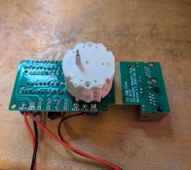
I tried to make the air gauge as self-contained as possible, and when making it compatible with Train Simulator (and my CAN bus) in December 2023, I was pleased to see that the CAN controller board fit neatly into the air gauge housing. Unfortunately, the axes of the X40 biaxial stepper motor are not in the center of the board, and I also needed to access the RJ-45 CAN bus ports, so I had to cut a hole in the side of the housing.
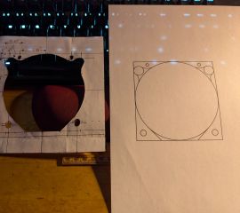
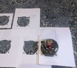
This was predicated on mounting the stepper motor directly on the CAN controller board, as designed, but when fellow hardware hacker geekboy1011 and I tried laser-cutting some plywood prototype panels into which to mount the components, we discovered that an extra hole had to be cut in the side of the aperture for the gauge to accommodate the circuit board as the gauge was inserted into the panel. Therefore, it became clear as I built paper, then cardboard prototypes of the dashboard increasingly close to 1:1 scale that I would need to reduce the external dimensions of the air gauge back to its original 2" radius. This was further driven home by determining exactly the template I would need to cut out of the dashboard to snugly fit the air gauge, which I did with a hand-drawn template followed by increasingly correct Inkscape drawings:
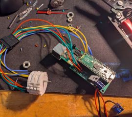
I therefore followed a straightforward, if delicate, series of steps to move the stepper motor off of the CAN controller:
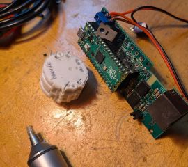
- I desoldered the stepper motor from the board, thanks to the excellent Japanese Engineer-brand SS-02 solder sucker that has served me very well over the past few years.
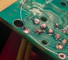
- I soldered wires in place of the now-removed 8 motor leads, using for the first time lead-free solder. This turned out to be the least trivial part of the project: having only used leaded solder in the past, properly using lead-free solder, including correct temperatures, was a learning curve. Thanks to guidance from geekboy1011, I zeroed in on some better practices: as the picture below shows, my earliest joints were overheated and poor, but my later joints improved.
- I crimped an 8-position JST-SM female male connector onto these wires, then crimped the matching female connector onto another set of 8 wires that I soldered onto the stepper motor, adding heat shrink tubing for mechanical stability.
- I could now mount the motor directly into the air gauge, on the back of the faceplate. Unfortunately, I didn’t have the long, very-thin-diameter screws I would have needed to use with the stepper’s own tiny mounting holes, so I instead used cyanoacrylate to glue the motor in place. I anticipate correcting this in the future.
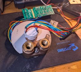
The resulting setup provided exactly what I needed: I can tuck the connector to the motor inside the gauge housing to insert it into the dashboard, screw it into place, then extract the connector and connect it to its CAN controller board, mounting the CAN controller board on the back of the dashboard. For a future iteration, I am considering alternatives that would allow the air gauge to be as self-contained as originally designed.
I could then test the result, connecting my CAN to USB serial bridge and writing a quick Python program to repeatedly move the MR and BP needles up and down along their range, graduating the backlight to match.
Testing the stepper motor control and backlight brightness


