Train Simulator Controller: Power/Brake Controller, Part 3
In my last two blog posts, I showed the Class 365 power/brake controller that I acquired from the UK, and how I reverse-engineered it and interfaced it with Train Simulator Classic. At the end of that second part, I could directly control a virtual Class 802 train in Train Simulator with the reverser and throttle/brake handles of the power/brake controller (PBC), but the interface circuit was an unwieldy combination of two breadboards end-to-end, a giant milspec socket, and one of the many CAN controller modules that are peppered throughout my nascent simulator setup. The next obvious task was to “miniaturize” the breadboard onto a circuit board, ideally one that could stack directly with my CAN controller.
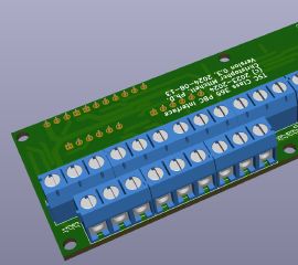
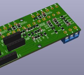
In fact, I had already completed a very similar design process with my speedometer, where I similarly designed and tested an interface circuit on a set of breadboards, fabricated a circuit board containing everything that had been on the breadboards, and gave it a simple stacking connector that allowed it to plug into both the speedometer’s 35-pin DIN socket and one of the CAN controllers. In this case, I put a series of screw terminals on one side of the board, and the many discrete components forming interfacing and protection circuits between the CAN controller and the PBC on the other side of the board.
I once again had the board made by JLCPCB and hand-soldered my components on: happily, I didn’t find any bugs in this board.
And with this, my Train Simulator setup gained another component. Personal and professional commitments would largely prevent me from making additional progress through the rest of the year, but in 2025 I plan to finish this first version of my simulator setup, and hopefully enjoy it for a while before feeling the need to tear it apart or upgrade it to version 2.


