Train Simulator Controller: Power/Brake Controller, Part 2
In my last blog post, I showed the Class 365 power/brake controller that I acquired from the UK, inside and out. I got it to control trains in Train Simulator, but all I had was the hardware itself, with no documentation, and no hardware to interface with it. I needed to first reverse-engineer the schematic and sequence diagram for the power/brake controller (PBC), then design and test how I would interface the PBC to Train Simulator.
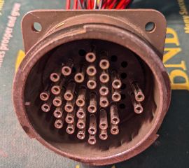
My process started with reverse-engineering the schematic for the PBC, including figuring out all the wires connected to its huge circular connector, shown below. Of the 48 possible pin positions in this milspec connector, 36 are populated, connected to 36 wires that lead to various of the 27 switches in the PBC. There’s also one wire that is only internally connected. I recorded the wire numbers for every switch, some of which are wired normally closed (NC), others normally open (NO), a task made much easier by Westinghouse labeling every wire internally. I then used a multimeter to buzz out all of the wires to the circular connector.
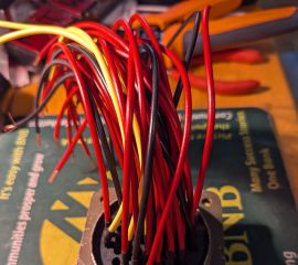
I wanted to interface it cleanly, using it as unmodified as possible. Therefore, my next step was to get or make a female connector to mate with the PBC’s male connector. I didn’t want to pay hundreds of dollars for a new female connector and pins, but eBay yielded a compatible (unpopulated) mating housing and the female pins I needed to populate it. And on a productive Saturday in August, I sat with the female pins, crimpers, spools of wire, and heat shrink tubing, and prepared and inserted all 36 female pins needed into the housing.
Of course, this huge connector needed to be interfaced with my CAN bus to which all of my instruments and controls are connected. I used the standard CAN bus transceiver that I built for every component of the simulation rig, and as with the speedometer, I developed a daughterboard to connect the PBC to the CAN bus transceiver. I initially anticipated that I would need to include a demultiplexer to interface the 36 wires connected to the 27 switches in the PBC, as the CAN bus transceiver has only 17 GPIO pins exposed. To determine if that was the case, I reverse-engineered a sequence diagram of how the 27 switches in the PBC open and close as the reverser and power/brake handles travel. I began this reverse-engineering simply from studying the actuator plates shown in the preceding blog post, then verified my results by hooking my multimeter up to each switch and running the handles through each position.
 Sequence diagrams for power/brake handle (left) and reverse (right)
After studying these sequence diagrams, I determined that I could detect all four different reverser positions, all 9 power/brake positions including emergency braking, and the holdover feature with only 15 GPIO pins. This simplified what interface hardware would be necessary, but with potentially noisy switches and long wires, I still wanted to make the daughterboard apply hardware debouncing to each switch. I also wanted to isolate the switches from the Raspberry Pi Pico on the CAN bus transceiver board, so I designed a circuit and printed circuit board with an RC low-pass filter and a simple transistor switch connected to each switch input. First I tested the circuit for a single switch on a breadboard (left), then built the full circuit for every switch (right):
This breadboarded circuit allowed me to fully test the interface and verify first that all connections to the PBC in the circuit design were correct, then that the debouncing and noise reduction circuitry was working as designed, and finally that the firmware on the CAN controller correctly interpreted the inputs from the PBC as accurate reverser, power, and brake settings. In fact, the primary bug that required tracing was in the software debouncing acting as a second layer after the hardware debouncing and denoising. This sample output from the debugging process shows the raw outputs from the switches (left column) followed by the interpreted level or value of the power, brake, reverser (direction), emergency brake, and brake holdover. Here is the output with both handles in the OFF positions.
 Debugging the firmware with debug printing from the CAN controller
With the interface hardware built, the firmware debugged, and my temporary Python driver that talks to Train Simulator updated, I could finally control a train with a real throttle/brake.


