Multichord

Overview
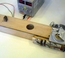
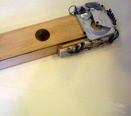
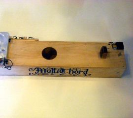
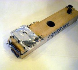
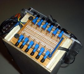
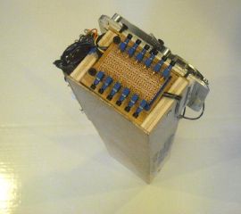
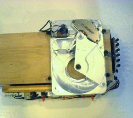
The Multichord musical instrument is an acoustic stringed instrument with a single string, constructed from wood, a hard drive, 20-lb monofilament, and assorted electronic components. It was the culmination of a project to build an acoustic instrument capable of playing multiple notes without fretting or manual, time-consuming retuning. The Multichord achieves this by attaching a hard drive read/write head assembly between the resonant string and a tensioning spring to adjust the tension of the instrument’s string. Careful adjustment was made to the tension of both the string and the spring with the hard drive head in a neutral, unpowered position to ensure a bipolar application of voltage within the safety ratings of the hard drive’s coil could cause the string to cover a full musical octave. In the end, the Multichord was tuned to a C-major scale (no flats or sharps) running from A at 220Hz through (but not including) A at 440Hz.
Table of Contents
Photos, Videos, Details
The Multichord project took about a month to complete, although in total in only cost about twenty to thirty hours of work. The base of the Multichord was a previous project called the Monochord, a purely-acoustic instrument with a single tensioned string and pencil markings for fretting to play an entire octave. However, I was displeased with the fretting process; a finger on the string would severely dampen the sound fom the open string, and even a piece of metal used to fret changed the timbre significantly. Therefore, I wanted to create an instrument that could electronically change the note that would be produced without changing the timbre of the instrument. Based on my knowledge of stringed instruments, I knew that changing the length of the resonant string or adjusting its tension both cause a change in the fundamental frequency produced when the string is plucked. Therefore, I disassembled a computer hard drive and mounted it on the end of the instrument in place of one anchor, leaving the other end as an adjustable tuning peg.
Because the steel string used in the original Monochord seemed far too hard for the hard drive to pull, it was replaced with a 20-lb monofilament thread, and a spring was attached to the hard drive head to counter the pull of the string. With the hard drive securely screwed onto the now-Multichord body, and the spring and string attached, it was time to begin tuning the instrument. A primary goal of the project was to be able to cover at least one octave, which was initially difficult with the limited length change and tension change that the hard drive’s read/write head is able to achieve. Extensive experimentation was done wherein the unpowered frequency of the string was checked with a spectrum analyzer, then the coil was powered with +12V and the frequency measured, then the process repeated with -12V. To cover a full octave, the frequency with -12V had to be at most half the frequency in Hertz at +12V, as each octave doubles the frequencies of the previous octave. Eventually a combination of initial string and spring tensions and resonant lengths was found that allowed notes from about 220Hz up to slightly under 440Hz. Because of later power losses that were found, the maximum voltage range turned out to be ±13.0V
Once the base frequency range was found, it was necessary to tune the instrument. Handily, the unpowered string was very close to 330Hz, the note E, so it was adjusted to this note. Then, the voltage was slowly adjusted between 0 and +13.0V for F and G, and between 0 and -13.0V for D, C, B, and A. The proper voltage values found are tabulated below.
| Note | Frequency (Hz) | Applied Voltage (V) | Resistance (Ω) | Nominal Current (A) |
|---|---|---|---|---|
| A | 220 | -13.0V | 0Ω | 1.18A |
| B | 247 | -10.5V | 2.6Ω | 0.77A |
| C | 262 | -8.3V | 6.3Ω | 0.48A |
| D | 294 | -4.6V | 20.0Ω | 0.15A |
| E | 330 | 0.0V | [inf]Ω | 0.0A |
| F | 349 | 2.8V | 40.0Ω | 0.05A |
| G | 392 | 9.1V | 4.7Ω | 0.58A |
As shown in the table, applied voltages to the coil varied from -13.0V through +9.1V in practice; +13.0V was insufficient to reach the A in the next octave, so this was omitted. As the coil was measured at 11.0Ω on its own, Rc =11.0Ω, and the supply voltage Vcc was set at 13.0V. From Ohm’s law, the total current flowing through the coil for any given resistance R=Rc +Rr , where Rr is a secondary 20W power resistor with the values given in the table above, is Vcc =IR=I(Rc +Rr ). This would be impossible to solve if we knew nothing else, since there are two unknowns (I and Rr ), but we know one other fact. We want to adjust the voltage drop over the coil Vc to each of the values in the table above, and we know its resistance is Rc =11.0Ω, so it follows (I being constant in a series loop) that Vc =11.0I and that I=Vc /11. Therefore, plugging this into the first equation, 13=(Vc /11)(11+Rr ). Simplification yields Rr =143/Vc -11. A chart of values for this equation from Vc =0 through Vc =13.0 was plotted in Matlab, and is shown below:

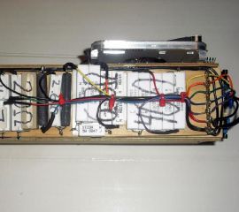
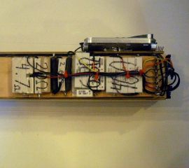
With all the resistor values picked, the next step was to construct the required resistances out of power resistors (20W). Normal 1/4W resistors could not be used because power dissipation approaches a maximum of 15.3W for an A note. The only resistors available were 0.33Ω, 0.47Ω, 2.0Ω, 8.0Ω, and a single 10.0Ω. The diagram below shows the resistor ladder networks generated for these values to produce each of the required resistance values:

Construction was then begun. The resistor networks were constructed and soldered, each was double-sided foam taped to a mounting board, and a header was added connected to each resistor. Next the button panel was soldered, with thick wires for as low resistance as possible. Finally, everything was mounted and the instrument was tested. To my great surprise, no adjustments were necessary. The final schematic for the Multichord is shown below:

More Information
Please be advised that the Multichord is a personal project, not a commercial offering. As such, no warranty is made to its fitness or appropriateness for any application or use. All information in this page from other sources has been properly attributed to the best of my knowledge, and if I am in error, please inform me at multichord@cemeetech.net, replacing the double e with a single e. Of course, as this page contains partial instructions for replicating my work, I and Cemetech disclaim any and all rsponsibility for damage, injury, etc resulting from following the instructions on this page or anywhere else on this site. If you try to make your own such instrument, you claim all responsibility for injury, damage, etc resulting from building or using the device. With that said, please be careful and use common sense; while the voltage and current involved in this project is not terribly large, you could still get a shock, and the use of objects under moderate to high tension presents a danger to you should any of the screws or other fastenings fail. Take appropriate caution, and don’t use power tools and power supplies without proper training or supervision. Oh, and be respectful of your components. Make sure you use resistors rated at high enough power, and be aware that this project is driving the hard drive coil way outside of its normal parameters. Do not keep powered tension on it for too long, or it will melt and short.
With all that boilerplate out of the way, please feel free to contact me about this project for more pictures, instructions, feedback, comments, or help with your own version. Your best bet is to write a post on the forums here, but failing that, try me at multichord@cemeetech.net, replacing the double e with a single e. Hope you enjoyed this!
Unless otherwise noted, all schematics, plans, instructions, and information on this page (c) 2009 Christopher Mitchell (Kerm Martian) and Cemetech. Except for fair use, this page or its embedded and attached information may not be reproduced without proper attribution to the author or the express written permission of the author.

